


ELECTRIC A'n'ACHMENT CLUTCHES
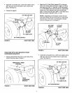
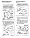
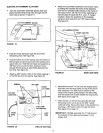
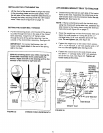
• Turn the clutch/idler assembly upside down and
place the extra tensioning chain through the left
front hole as shown in figure 19.
/
TENSIONING CHAIN
FIGURE 19
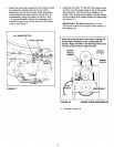
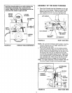
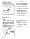
Hook the loose spring through the end of the
tensioning chain. See figure 20.
Hook the other end of the spring onto the bottom of
the bolt and nut which secure the idler pulley to the
upper idler arm. Hold the bolt head and assemble a
3/8" hex lock nut onto the bolt, leaving it loose
enough for the spring to pivot freely between the
two nuts. See figure 20.
Attach a 3/32" hairpin cotter to the chain, placing it
in the fifth link from the spring. See figure 20.
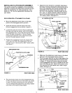
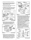
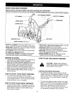
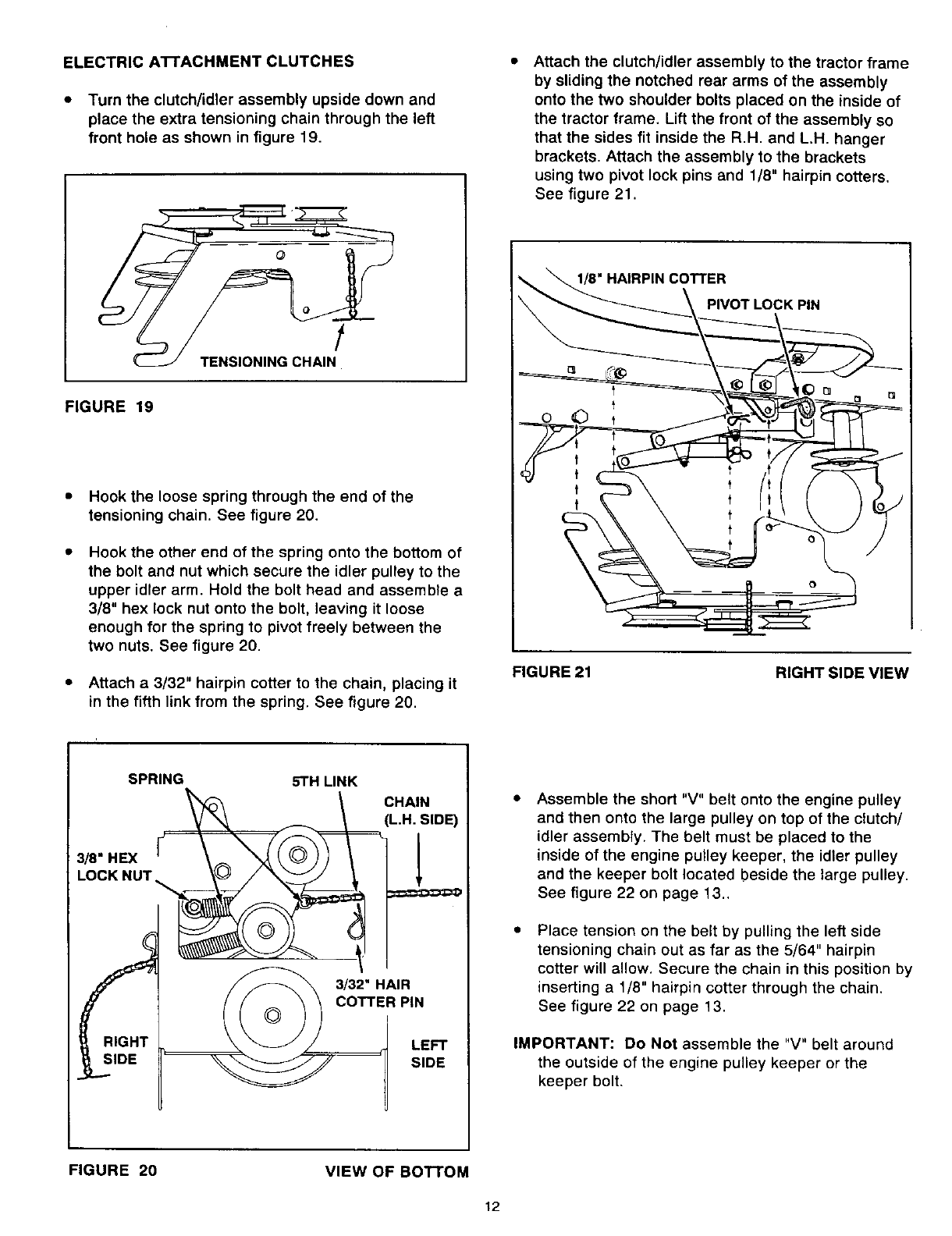
• Attach the clutch/idler assembly to the tractor frame
by sliding the notched rear arms of the assembly
onto the two shoulder bolts placed on the inside of
the tractor frame. Lift the front of the assembly so
that the sides fit inside the R.H. and L.H. hanger
brackets. Attach the assembly to the brackets
using two pivot lock pins and 1/8" hairpin cotters.
See figure 21.
1/8" HAIRPIN COTTER
PIVOT LOCK PIN
FIGURE 21
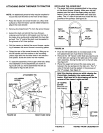
RIGHT SIDE VIEW
RIGHT
SIDE
CHAIN
L..H.SIDE)
3/32" HAIR
COTTER PIN
LEFT
SIDE
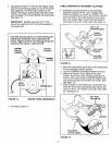
Assemble the short "V" belt onto the engine pulley
and then onto the large pulley on top of the clutch/
idler assembly. The belt must be placed to the
inside of the engine pulley keeper, the idler pulley
and the keeper bolt located beside the large pulley.
See figure 22 on page 13..
Place tension on the belt by pulling the left side
tensioning chain out as far as the 5/64" hairpin
cotter will allow. Secure the chain in this position by
inserting a 1/8" hairpin cotter through the chain.
See figure 22 on page 13.
IMPORTANT: Do Not assemble the "V" belt around
the outside of the engine pulley keeper or the
keeper bolt.
FIGURE 20
VIEW OF BOTTOM
12