


INSTALLING CLUTCH/IDLER ASSEMBLY
This section covers the installation of the Clutch/Idler
assembly to tractors with attachment clutches that are
either rod operated (p, 9), cable operated (p. 10) or
electric (p. 12). Use the appropriate instructions for
your tractor.
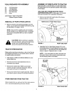
ROD OPERATED ATTACHMENT CLUTCHES
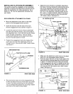
• Move the attachment clutch lever on the dash
panel to the disengaged (down) position.
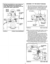
Screw the trunnion onto the end of the snow
thrower engagement rod as shown in figure 11.
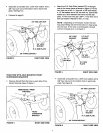
Locate the clutch arm which is found underneath
the right hand side the tractor, just to the inside of
the suspension arm. This is the arm that the mower
clutch rod was connected to. The arm moves
forward and backward as the attachment clutch
lever on the dash panel is moved.
Position the engagement rod to the inside of the
clutch arm and insert the drilled end of the rod
through the arm. Secure with a 5/64" hairpin cotter.
See figure 11.
ENGAGEMENTROD
TRACTOR'S CLUTCH ARM
/
5/64" HAIRPIN
COTTER
\
SUSPENSION ARM
FIGURE 11
RIGHT SIDE VIEW
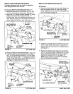
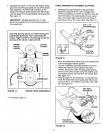
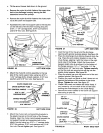
Be sure that the loose end of the engagement rod
is lifted up toward the front of the tractor (as shown
in figure 12) when performing the next operation.
You can temporarily support the rod using a rubber
band tied to the engine pulley keeper.
Attach the snow thrower's clutch/idler assembly to
the tractor frame by sliding the notched arms at the
rear of the assembly onto the two shoulder bolts
assembled to the inside of the tractor frame. Lift
the front of the assembly, fitting the sides into the
R.H. and L.H. hanger brackets. Attach the assem-
bly to the brackets using two pivot lock pins and
1/8" hairpin cotters. See figure 12.
1/8" HAIRPIN COTTER
PIVOT LOCK PIN
ENGAGEMENT
ROD
FIGURE 12
RIGHT SIDE VIEW
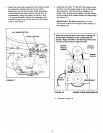
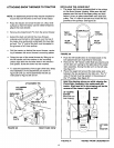
Make sure the attachment clutch lever on the dash
panel is in the disengaged (down) position.
Pivot the upper idler arm so that it rests against the
stop bolt and is pointing toward the front as shown
in figure 13. Screw the trunnion along the threads
of the engagement rod until it is aligned at the front
end of the idler arm slot. Attach the trunnion to the
slot using the 3/8" flat washer and a 5/64" hairpin
cotter. See figure 13.
FIGURE 13
IDLER ARM
3/8" FLAT
_ WASHER
5/64" HAIRPIN
COTTER
RIGHT SIDE VIEW