


6
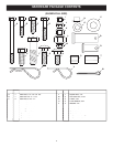
(1) Pliers
(1) Hammer
(1) Adjustable Wrench (or socket set)
(1) 9/16" Open End or Box End Wrench
(2) 7/16" Open End or Box End Wrench
(2) 1/2" Open End or Box End Wrench
TOOLS REQUIRED FOR ASSEMBLY
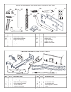
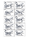
REMOVAL OF PARTS FROM CARTON
•
Remove the loose parts and the hardware packages
from the carton. Lay out all parts and hardware and
identify using the illustrations on pages 4 and 5.
IMPORTANT:
You will not use all of the parts or hardware
supplied with your blade. Dispose of unused parts or
hardware after you have fi nished assembling the blade.
CAUTION:
Do not
begin assembling
until the tractor engine, muffl er and exhaust
defl ector have been allowed to cool off.
TRACTOR PREPARATION
•
Allow engine, muffl er and exhaust defl ector to cool
before beginning.
•
Refer to tractor owner's manual to remove mower
deck or any other attachment you may have mounted
to your tractor. Mark and save all removed parts.
IMPORTANT:
Right hand (R.H.) and left hand (L.H.) are
determined from the operators position while seated on
the tractor.
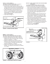
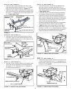
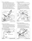
STEP 1: (SEE FIGURE 1)
•
Look
under the front of your tractor
Look under the front of your tractorLook
. I
f there is a single
mower deck suspen
sion bracket located
underneath
the mi
dd
le of the front axle, continue
on to step
2
.
I
f
not
, skip to step 7 on page 8 for tractors with dual
mower deck suspension brackets.
MOWER DECK
SUSPENSION
BRACKET
FIGURE 1 - SEARS TRACTOR SHOWN
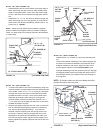
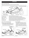
3/8" LOCK WASHER (O)
3/8" X 1" HEX BOLT (E)
FRAME BRACKET
3/8" NYLON
LOCK NUT (K)
3/8" X 1"
CARRIAGE BOLT (H)
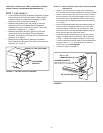
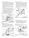
FIGURE 2 - SEARS TRACTOR SHOWN
REMOVE BROWNING
SHIELD ON SEARS
TRACTORS
MOUNTING
HOLES ON
SEARS TRACTORS
FRAME
BRACKET
FIGURE 3 - SEARS TRACTOR SHOWN
STEP 3: (SEE FIGURE 3)
•
Attach
a frame bracket to each sid
e of the tractor
frame. On Sears tractors use a 3/8" x 1" hex bolt
(E) and 3/8" lock washer (O) in the lower hole and a
3/8" x 1" carriage bolt (H) and 3/8" nylock nut (K) in
the upper hole of each frame bracket. Leave out the
upper bolt if there is no hole in the tractor frame.
Do
not tighten.
For other brand tractors use the bolts
and nuts shown in the illustrations on page 9.
• On Sears tractors re-attach
the bro
wning shield
.
STEP 2: (SEE FIGURE 2)
•
Use fi gure 2 to help i
dentify the mounting holes for
Sears tractor frames.
For other brand tractors
, identify
the two mounting holes by p
lacing a frame bracket
against the tractor frame
in front
of
the front axle and
fi nding two holes in the tractor frame that align with
two of the holes in the frame bracket
.
T
he bracket can
be fl
ipped over to reverse the
hole pattern.
R
efer also
to the illustrations on page
9
.
• Remove any bolts found in the mounting holes.
• On Sears tractors, remove the browning shield from
the front of the tractor as shown.
IMPORTANT:
Be sure to reattach
the browning shield in
step 3
.
INSTRUCTIONS FOR TRACTORS WITH SINGLE
FRONT DECK SUSPENSION BRACKETS
OPERATION