


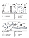
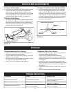

13
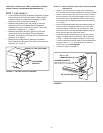
FIGURE 24
(Left Hand Side View)
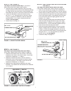
FIGURE 22 (Right Hand Side View)
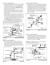
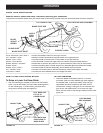
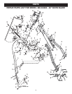
STEP 21:
(SEE FIGURE 21)
•
From the left side, insert the welded end of the lift
handle rod through the exposed holes in the end of
the channel assembly. Next, insert the lift link pin
through the hole in the bracket that is welded to the lift
handle rod. (The lift link is pre-assembled to the pivot
support bracket). Secure the bracket with a small
hairpin cotter (V) inserted up through the lift link pin all
the way to the loop end of the hair pin cotter.
•
Using the furnished grease packet, apply a light
coating of grease to the straight upper portion of the
lift handle rod. Slide the lift handle tube onto the rod.
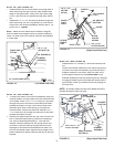
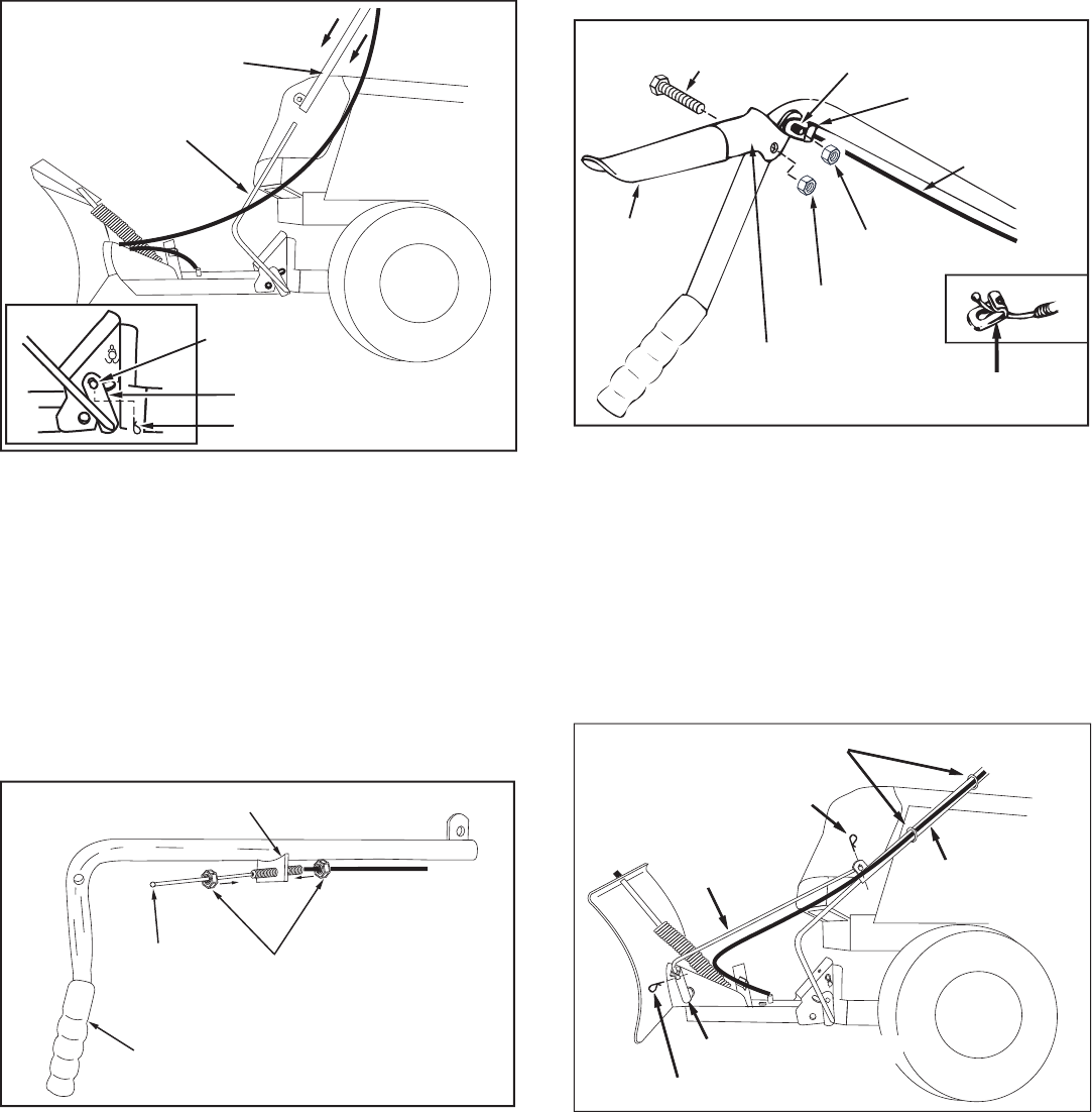
STEP 24:
(SEE FIGURE 24)
•
Place the long end of the blade pivot rod down
through the blade pivot shaft. Attach the short end of
the blade pivot rod to the lift handle tube. Secure both
ends with small hairpin cotters (V).
•
Use the two plastic ties to hold the cable securely
to the outside of the handle tube and away from the
tractor to avoid direct heat from the tractor muffl er.
FIGURE 23
(Right Hand Side View)
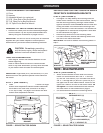
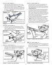
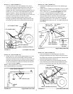
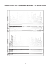
STEP 22:
(SEE FIGURE 20)
•
Screw one 5/16" jam nut (M) approximately 3/4" onto
the loose end of the control cable. Pass the cable
around the outside of the lift handle rod and insert the
threaded cable end through the cable mount bracket
on the lift handle tube. Secure the cable with another
5/16" jam nut (M).
Tighten
.
NOTE:
Some adjustment of jam nuts may be required
after blade assembly is completed.
HANDLE
GRIP
BALL
END
CABLE MOUNT BRACKET
5/16" JAM NUTS (M)
5/16" x 1-1/2"
HEX BOLT (D)
PLASTIC
GRIP
LOCK RELEASE
GRIP ASSEMBLY
1/4" WELD
BOLT
CABLE END
FITTING
5/16" NYLOCK
NUT (J)
1/4 " NYLOCK
NUT (I)
CABLE
FIGURE 21
(Left Hand Side View)
LIFT HANDLE ROD
SMALL HAIRPIN COTTER (V)
LONG PIN
(LIFT LINK)
WELDED BRACKET
LIFT HANDLE TUBE
CABLE END
FITTING
BLADE
PIVOT
ROD
LIFT HANDLE
TUBE
SMALL HAIRPIN
COTTER (V)
SMALL HAIRPIN COTTER (V)
PLASTIC TIES
BLADE PIVOT SHAFT
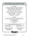
STEP 23:
(SEE FIGURE 23)
•
Assemble the plastic grip onto the lock release grip
assembly.
•
Attach the lock release grip assembly to the lift handle
tube using one 5/16" x 1-1/2" hex bolt (D) and one
5/16" nylock nut (J).
Do not overtighten
the nylon
lock nut. The grip assembly must pivot freely.
•
Assemble the ball end of the cable to a cable end
fi tting as was done to the other end of the cable.
Secure the cable end fi tting to the weld bolt on the
lock release grip with a 1/4" nylock nut (I).
Do not
overtighten
the nylon lock nut. The cable fi tting must
pivot freely.
CABLE END
FITTING