


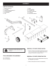
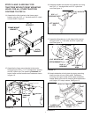
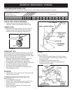

7
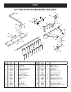
17. Assemble lift handle arm to left side of hitch bracket
using two 5/16" x 1" hex bolts and 5/16" nylock hex
nuts. See gure 12.
FIGURE 12
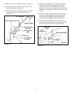
18. Attach dethatcher to hitch plate by placing mounting
shaft into slots at front of hitch plate. Dethatcher
mounting arms go to inside of hitch plate. Assemble
keeper plates onto ends of mounting shaft and secure
with (large) 1/8" hairpin cotters. See gure 13.
FIGURE 13
HITCH BRACKET
5/16" NYLOCK NUT
5/16" x 1"
HEX BOLT
LIFT HANDLE
ARM
FRONT
FRONT OF TRACTOR
HITCH
PLATE
SLOT
(LARGE) 1/8"
HAIRPIN COTTER
KEEPER
PLATE
MOUNTING
SHAFT
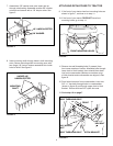
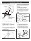
16. Assemble handle lock bracket to lift handle arm using
two 5/16" x 1" carriage bolts and 5/16" nylock hex
nuts. See gure 11.
FIGURE 11
5/16" NYLOCK
NUT
5/16" x 1"
CARRIAGE BOLT
LIFT HANDLE
ARM
HITCH
BRACKET
FRAME MOUNT
BRACKET
3/8" x 1"
HEX BOLT
3/8" NYLOCK
NUT
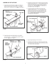
14. Assemble the hitch bracket to the frame mount
bracket using four 3/8" x 1" hex bolts and 3/8" nylock
nuts as shown in gure 9.
15. Assemble the frame mount bracket to the tractor
frame using four 3/8" x 1-1/2" carriage bolts, spacers
and 3/8" nylock nuts. The spacers go between the
tractor frame and the frame mount bracket as shown
in gure 10.
FIGURE 9
FIGURE 10
SPACER
3/8" NYLOCK
NUT
3/8" x 1-1/2"
CARRIAGE
BOLT
STEPS 14 AND 15 ARE ONLY FOR
TRACTORS WITHOUT FRONT MOUNTING
HOLES. FOR ALL OTHER TRACTORS
CONTINUE TO STEP 16.