10
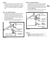
FIGURE 18
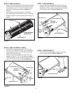
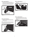
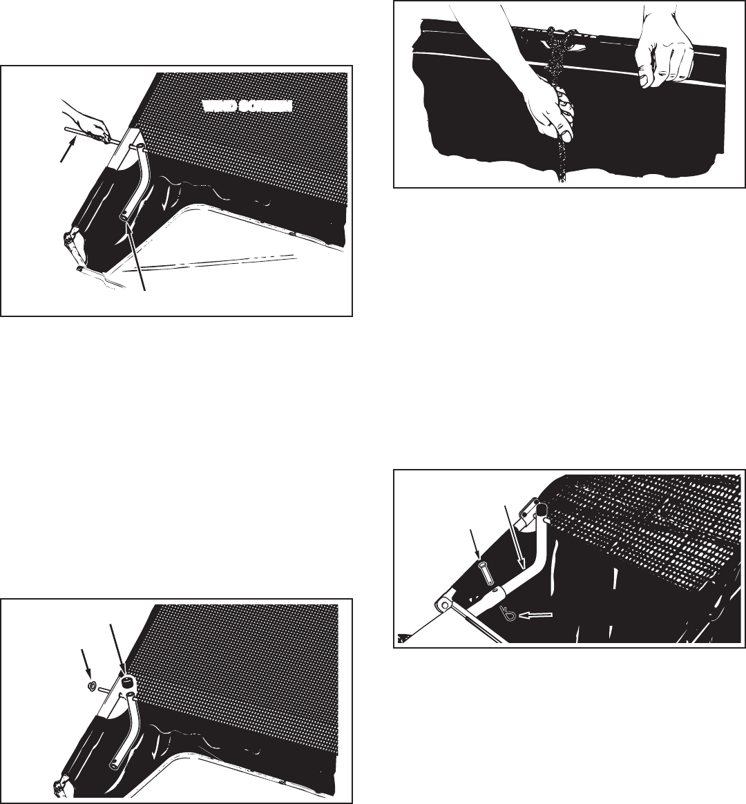
STEP 19: (SEE FIGURE 17)
• Slidetheendofthepivotrodthroughtheupper
hoppertube.Placeabagarmtubeontotherod.Slide
therodthroughthestitchedsleeveatthefrontedge
ofthewindscreen,andthenplaceanotherbagarm
tubeontotherod.Slidetherodthroughtheother
upperhoppertube.
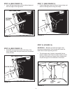
STEP 22: (SEE FIGURE 20)
• Toattachthehopperbagtothesweeper,slidethe
endsofthebagarmtubesintotheendsofthehitch
tubesandsecurewithtwoclevispins(J)andhairpin
cotters(M).
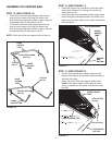
STEP 21: (SEE FIGURE 19)
• Secure the rope to the center of the upper rear
hoppertube.
FIGURE 20
STEP 20: (SEE FIGURE 18)
• Assembleavinylcap(O)ontoeachbagarmtube.
• Assembletwopalnuts(H)ontotheendsofthepivot
rod using a hammer.
HINT: Toeaseassemblyofthepalnuts,placethebag
onitssideonasolidsurface.Withthebottomendofthe
pivotrodagainstthesurface,tapapalnutontothetop
end of the rod. Repeat for other end of rod.
FIGURE 17
FIGURE 19
BAG ARM TUBE
HOPPER BAG
PIVOT ROD
MOUNTING CLAMP MOUNTING CLAMP
WIND SCREEN WIND SCREEN
MOUNTING CLAMP MOUNTING CLAMP
PALNUT (H)
CAP (O)
CLEVIS PIN (J)
BAG ARM TUBE
HAIRPIN
COTTER (M)


