


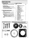
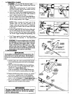
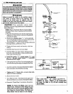
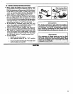
2. THROTTLE C_,dlll-_
_r.._IYI'ION:3 Do not kink the throttle cable ....... i
a: SlideFoamtheThrottleGrip. Trigger Housing away from the . ,_ _1 IIJ_r-I_ _ltf ....
'NOTE: Before performing step "b", push the barrel _ 0'__
_the throttle cable into the sheath until the _ ] [,,I,_q¢
barrel contacts the sheath. ' ! _.._'€_ I \,
b Insert the Throttle Cable through the tunnel in _he no, rsnno'_ Jl \
Foam Grip until the end of the Cable extends at ...... N: .... ],], aAu_n_
least 2 inches beyond :the Grip. TRIGGER j ], I _I_O'F"
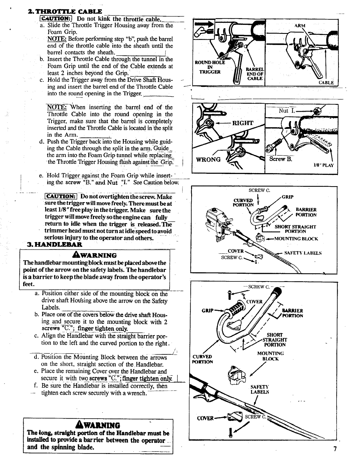
c. Hold the Trigger away from the Drive Shaft Hous- -I- _._ C._LZ
ing and insert the barrel end of the Throttle Cable , '......................7--
into the round_ opening in the Trigger._.
-_-_E.:--°When inserting the barre! end °ft-he
Throttle Cable into the round opening in the
Trigger, make sure that the barrel is completely
inserted and the Throttle Cable is located in 'the split
in the Arm.
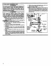
d. Push the Trigger back into the Housing while guid -
ing the Cable through the split in the art 9. Guide_
the arm into the Foam Grip tunnel while replacing,
the Throttle Trigger Housing trash againstthe Grip__
e. Hold Trigger_against the Foam Grip while insert-"
ing the screw "B." and Nut "I." See Caution below.
[CAUTION: ('Do notovertig-htenihe screw. Make
sure the trigger will move freely. There must be at •
least 1!8"free play in the trigger. Make sure the
trigger will move freely so the engine can fully
return to idle when the trigger is released. The--
trimmer head must not turn at idle_speed to avoid
serious injury to the operator and others.
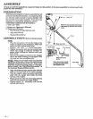
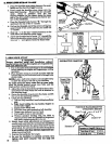
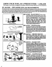
3. HANDLEBAR •
ARM
Nut
alXWARNING
The handlebar mountingblock must be placed above the
point of the arrow on the safety labels. The handlebar
is a barrier to keep the blade away from the operator's
feet.
a. Position either side of the mounting block on the
drive shaft Housing above the arrow on the Safety
Labels.
b. Place one of the covers below the drive shaft Hous-
ing and secure it to the mounting block with 2
c. Align the Handlebar with the straight barrier por-
tion to the left and the curved portion to the right. _
d. Position the Mounting Block between the arrows
on the short, straight section of the Handlebar.
e. Place the remaining Cover over the Handlebar and
secur e it with two_re__WSs_iC_":,finger tightenordy.- [ .
f. Be sure the Handlebar is installed correctly, then
.... tighten each screw securely with a wrench.
AWMUIDI0
The long, straight portion of the Handlebar must be
installed to provide a barrier between the operator
and the spinning blade.
SAFETY
LABELS
/
:C
CABLE