


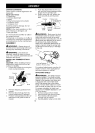

CARTONCONTENTS
Checkcartoncontentsagainstthefol-
lowinglist.
Model 358,791072
• Powerhead
• Trimmer attachment
• Shield
• Wing Nut (screwed onto shield)
• Container of line
• Container of oil
Examine parts for damage. Do not
use damaged parts.
NOTE: If you need assistance or find
parts missing or damaged, call
1-800-235-5878.
It is normal for the fuel filter to rattle in
the empty fuel tank.
Finding fuel or oil residue on muffler is
normal due to carburetor adjustments
and testing done by the manufacturer.
ASSEMBLY
,_WARNING: Always stop unit
and disconnect spark plug before per-
forming any assembly procedures.
WARNING: If received as-
sembled, repeat all steps to ensure
your unit is properly assembled and all
fasteners are secure.
INSTALLING TRIMMER ATTACH-
MENT
CAUTION: When installing trimmer
attachment, place the unit on a flat
surface for stability.
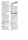
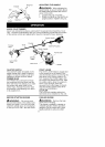
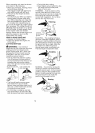
1. Loosen the coupler by turning the
knob counterclockwise.
Coupler
Shipping
protector
LOOSEN
Knob
TIGHTEN
2. Remove shipping protector from
coupler.
3. Remove the shaft cap from the
trimmer attachment (if present).
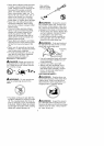
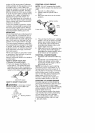
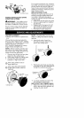
4. Position locking/release button of
attachment into guide recess of
coupler.
5. Push the attachment into the cou-
pler until the locking/release button
snaps into the primary hole.
6. Before using the unit, tighten the
knob securely by turning clock-
wise.
Coupler Primary Hole
\ / Guide Recess
U I Lookingl ^,_',__,."___,"
pper Release Attachment
Shaft
Button
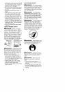
nWARNING: Make sure the lock-
ing/release button is locked in the pri-
mary hole and the knob is securely
tightened before operating the unit. All
attachments are designed to be used in
the primary hole unless otherwise
stated in the applicable attachment op-
erator's manual. Using the wrong hole
could lead to serious injury or damage
to the unit.
Secondary Hole
Locking/Release
Button in Primary Hole
For optional attachments, see the AS-
SEMBLY section of the applicable at-
tachment operator's manual.
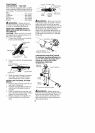
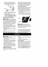
ATTACHING SHIELD
_&WARNING: The shield must be
properly installed. The shield provides
partial protection from the risk of thrown
objects to the operator and others and
is equipped with a line limiter blade
which cuts excess line to the proper
length. The line limiter blade (on under-
side of shield) is sharp and can cut you.
For proper orientation of shield, see
KNOW YOUR TRIMMER illustration in OP-
ERATION section.
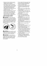
1. Remove wing nut from shield.
2. Insert bracket into slot as shown.
3. Pivot shield until bolt passes
through hole in bracket.
4. Securely tighten wing nut onto bolt.
10