


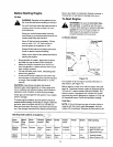
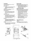
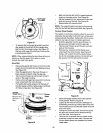

Drive Belt
Figure 27
To remove thefront auger drive belt, push the
idler pulley to the left and lift front auger drive
belt from the front auger pulley. See Figure 27.
Replace both auger drive belts by following the
preceding instructions.
NOTE: When reassembling the two halves of the unit,
make sure that the auger drive cable is routed
through the cable roller guide.
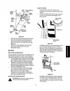
Drive Belt
• Remove the plastic belt cover on the frontof the
engine by removing the two self-tapping screws.
See Figure 25.
• Drain the gasoline from the snow thrower, or
place a piece of plastic under the gas cap.
• Tip the snow thrower up and forward so that it
rests on the auger housing.
Remove four self-tapping screws from the frame
cover underneath the snow thrower.
• Pulling the idler pulley upward, roll the belt off
the idler pulley and the engine pulley and lift belt
off friction wheel disc. See Figure 28.
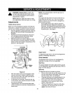
Friction
Wheel Disc Friction
Remove Wheel
here
Auger
Support
Bracket
Figure 28
Back out the stop bolt until the support bracket
drops on the auger pulley. See Figure 28.
Slip belt between friction wheel and friction disc
plate and remove the belt. See Figure 28.
Reassemble with new drive belt.
NOTE: The support bracket must rest on the stop bolt
after the new belt has been assembled. See Figure 28.
Friction Wheel Rubber
The rubber on the friction wheel is subject to wear and
should be checked after the first 25 hours of operation
and periodically thereafter. Replace the friction wheel
rubber if any signs of wear or cracking are found.
• Drain the gasoline from the snow thrower, or
place a pieceof plasticunder the gas cap.
• Tip the snow thrower up and forward, so that it
rests on the housing.
• Remove four screws from the frame cover
underneath the snow thrower. See Figure 25.
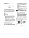
• Using a 7/8" wrench to hold the shaft, loosen,
but do not completely remove, the hex bolt and
bell washer from the left end of the shaft.
BellWasher
Hex Bolt
Figure 29
Move the weight transfer lever to the packed
snow position. Refer to Figure 18.
Lightly tap the head of the bolt to dislodge the
ball bearing from the right side of the frame; then
remove the hex bolt and the bell washer from left
end of the shaft.
Sliding the shaft to the right, remove the spacer,
the sprocket and the friction wheel assembly
from the shaft. See Figure 30.
Remove the six screws from the friction wheel
assembly (three from each side). Remove the
friction wheel rubber from between the friction
wheel plate.
22