


19
20
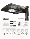
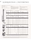
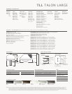
ALUMINUM POLES + PHOTOMETRICS
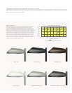
ALUMINUM POLES [Specification Features]
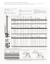
ROUND STRAIGHT ALUMINUM [RSA]
Fixture Mounting
Drilled or Tenon [Must specify].
Shaft
6005-T6 aluminum alloy with polished finish.
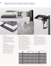
Handhole
Flush reinforced 2 3/8" x 4 1/2" for 4" shafts.
Handhole assembly with internal reinforcing
frame. 3" X 5" for 6" shafts, 4" x 6" for 7", 8"
and 10" shafts. Ground lug located opposite
handhole opening drilled & tapped for 3/8"
16NC-2 grounding screw.
Base
356-T6 cast aluminum alloy shoe base with
aluminum alloy knock-in bolt covers or base
cover dependent on base type.
Anchorage
Anchor bolt per ASTM A576 with [1] nut, [1] flat
washer, and [2] shims. Nuts, washers and
threaded portion of bolt are hot dip galvanized.
WARNING: THE USE OF UNAUTHORIZED ACCESSORIES SUCH AS BANNERS, SIGNS OR PENNANTS FOR WHICH THE POLE WAS NOT DESIGNED VOIDS THE COOPER LIGHTING WARRANTY AND MAY RESULT IN POLE
FAILURE CAUSING SERIOUS INJURY OR PROPERTY DAMAGE. COOPER LIGHTING'S POLE WARRANTY IS ALSO VOIDED IF THE LUMINAIRE IS NOT INSTALLED AT TIME OF POLE INSTALLATION. THIS WARRANTY
SPECIFICALLY EXCLUDES FAILURE AS THE RESULT OF A THIRD PARTY ACT OR OMISSION, MISUSE, UNANTICIPATED USES, FATIGUE FAILURE OR SIMILAR PHENOMENA RESULTING FROM INDUCED
VIBRATION, HARMONIC OSCILLATION OR RESONANCE ASSOCIATED WITH MOVEMENT OF AIR CURRENTS AROUND THE PRODUCT.
Bolt Anchor
Mtg. Wall Shaft Bolt Circle Bolt Net. Max.
Height Catalog Thickness Dia. Proj. Dia. Dia. & Wt. EPA [Sq. Ft.]
3, 4
Load
[Ft.] Number
1
[In.] [In.] [In.] [In.] Length [In.] [Lbs.] At Pole Top [Lbs.]
MH B BP BC D x AB x H 70 80 90 100
15 RSA4M15N .188 4 1 7/8 6 3/4 3/4 x 17 x 3 33 6.4 4.2 2.8 1.8 100
15 RSA5T15N .125 5 1 7/8 7 3/4 3/4 x 17 x 3 40 11.5 8.2 6.2 4.9 100
18 RSA4M18N
2
.188 4 1 7/8 6 3/4 3/4 x 17 x 3 54 7.2 4.8 3.1 2.1 100
18 RSA5M18N .188 5 1 7/8 7 3/4 3/4 x 17 x 3 66 13.0 9.2 7.0 5.5 150
20 RSA5M20N .188 5 1 7/8 7 3/4 3/4 x 17 x 3 73 10.3 7.1 5.3 4.1 150
ROUND TAPERED ALUMINUM [RTA]
Base Bolt Anchor
Mtg. Wall Dia. or Shaft Bolt Circle Bolt Net. Max.
Height Catalog Thickness Square Dia. Proj. Dia. Dia. & Wt. EPA [Sq. Ft.]
3, 4
Load
[Ft.] Number
1
[In.] [In.] [In.] [In.] [In.] Length [In.] [Lbs.] At Pole Top [Lbs.]
MH B BP BC D x AB x H 70 80 90 100
12 RTA4T12N .125 9 1/4 4 x 3 1 7/8 6 3/4 3/4 x 17 x 3 25 10.1 7.3 5.3 4.0 100
15 RTA4T15N .125 9 1/4 4 x 3 1 7/8 6 3/4 3/4 x 17 x 3 30 7.0 4.8 3.3 2.3 100
15 RTA5T15N .125 10 1/2 5 x 3 1 7/8 7 3/4 3/4 x 17 x 3 33 12.7 9.1 6.7 5.1 100
18 RTA5T18N .125 10 1/2 5 x 3 1 7/8 7 3/4 3/4 x 17 x 3 39 8.8 6.0 4.3 3.1 100
18 RTA6L18A .156 10 1/4 6 x 4 2 1/8 9 3/8 3/4 x 17 x 3 57 18.2 13.3 10.2 8.0 100
20 RTA5T20N .125 9 1/4 5 x 3 1 7/8 8 1/2 3/4 x 17 x 3 43 7.0 4.6 3.1 2.1 100
20 RTA6L20A .156 10 1/4 6 x 4 2 1/8 9 3/8 3/4 x 17 x 3 64 14.7 10.6 7.9 6.2 150
25 RTA6L25A
2
.156 10 1/4 6 x 4 2 1/8 9 3/8 3/4 x 17 x 3 81 8.8 5.9 4.1 3.0 150
25 RTA8L25A
2
.156 11 5/8 8 x 4 1/2 2 3/4 11 1/2 1 x 36 x 4 106 20.3 15.0 11.5 9.0 200
30 RTA7L30A
2
.156 10 5/8 7 x 4 2 3/4 10 1/2 1 x 36 x 4 108 9.0 5.9 4.1 3.0 150
30 RTA8L30A
2
.156 11 5/8 8 x 4 1/2 2 3/4 11 1/2 1 x 36 x 4 117 13.5 9.6 7.2 5.5 200
30 RTA0L30A
2
.156 14 1/2 10 x 6 2 7/8 14 1/2 1 x 36 x 4 152 25.8 19.3 14.8 11.5 250
35 RTA8L35A
2
.156 11 5/8 8 x 4 1/2 2 3/4 11 1/2 1 x 36 x 4 140 9.0 6.0 4.3 3.1 150
35 RTA0L35A
2
.156 14 1/2 10 x 6 2 7/8 14 1/2 1 x 36 x 4 180 19.0 14.0 10.5 8.0 200
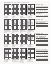
SQUARE STRAIGHT ALUMINUM [SSA]
Bolt Anchor
Mtg. Wall Shaft Bolt Circle Bolt Net. Max.
Height Catalog Thickness Dia. Proj. Dia. Dia. & Wt. EPA [Sq. Ft.]
3, 4
Load
[Ft.] Number
1
[In.] [In.] [In.] [In.] Length [In.] [Lbs.] At Pole Top [Lbs.]
MH B BP BC D x AB x H 70 80 90 100
12 SSA4T12W .125 4 1 3/4 9 3/4 x 17 x 3 32 16.0 11.5 8.5 6.3 260
15 SSA4T15W .125 4 1 3/4 9 3/4 x 17 x 3 39 9.1 6.2 4.2 2.8 200
15 SSA4M15W .188 4 1 3/4 9 3/4 x 17 x 3 55 14.8 10.6 7.7 5.6 200
15 SSA5T15W .125 5 2 11 3/4 x 17 x 3 52 16.0 11.3 8.1 5.8 260
18 SSA4T18W .125 4 1 3/4 9 3/4 x 17 x 3 46 6.4 4.0 2.3 1.1 100
18 SSA4M18W .188 4 1 3/4 9 3/4 x 17 x 3 66 11.0 7.4 5.0 3.3 150
18 SSA5T18W .125 5 2 11 3/4 x 17 x 3 61 11.8 7.8 5.1 3.2 150
18 SSA5M18W .188 5 2 11 3/4 x 17 x 3 85 19.2 13.5 9.6 6.8 260
20 SSA4M20W .188 4 1 3/4 9 3/4 x 17 x 3 72 8.8 5.6 3.5 1.9 150
20 SSA5T20W .125 5 2 11 3/4 x 17 x 3 66 9.5 5.9 3.5 1.7 100
20 SSA5M20W .188 5 2 11 3/4 x 17 x 3 94 16.4 11.2 7.6 5.0 150
25 SSA5M25W .188 5 2 11 3/4 x 17 x 3 115 10.2 6.0 3.2 1.1 100
25 SSA6M25W .188 6 2 12 1/2 1 x 36 x 4 140 16.6 10.6 6.5 3.5 260
30 SSA6X30W .250 6 2 12 1/2 1 x 36 x 4 215 14.8 9.0 5.0 2.1 260
30 SSA9X30W .250 6 3/4 2 3/4 14 1/4 1 x 36 x 4 237 21.1 13.5 8.2 4.5 260
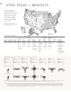
NOTES: 1 Catalog number does not include anchor bolts. 2 Factory installed vibration dampeners. 3 Where higher EPA/wind speed capability or mounting height is required,
other shaft dimensions and/or wall thickness are available. Consult Cooper Lighting representative for pricing and lead times. The above E.P.A. capacities are based on
loading from [1994] and pole drag coefficients from [2001] American Association of State Highway and Transportation Officials Specification. 4 EPAs based on shaft
properties with wind normal to flat. EPAs calculated using base wind velocity as indicated plus 30% gust factor.
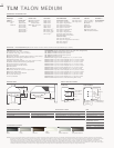
Handhole
18"
Base
Square
[S]
Shaft Size [B]
Square
Round
Handhole
12 5/16 "
Fixed Tenon
or Drilled
Mtg.
Ht.
[MH]
[AB]
[BP]
[H]
[D]
Base
Square
[S]
Round Straight
Shaft Size [B]
[BC]
[BC]