


17
18
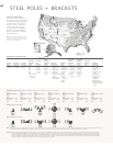
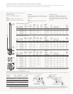
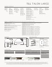
STEEL POLES + BRACKETS
ORDERING INFORMATION
SAMPLE NUMBER: RSS4A20SFM2XG
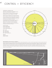
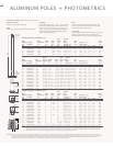
ISOTACH WIND MAP
This map has been included to
aid in pole selection with regard
to geographic location. Although
a less stringent 25-year mean
recurrence map is sometimes
used by other pole suppliers,
it is our belief that the added
measure of assurance offered
with the use of this map deems
it more desirable.
NOTE: This wind map is intended as a general
guideline only. Consult local engineering
standards to determine the exact wind loading
conditions for your application.
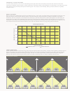
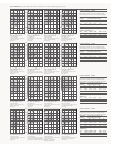
FIXTURE DRILLING [Note handhole position relative to drill locations]
“M2”
Arm Mount 2 @ 180°
E.P.A.
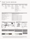
TLM
Recessed Door 2.44
Deep Door 2.90
TLL 5.02
“M1”
Arm Mount Single
E.P.A.
TLM
Recessed Door 1.22
Deep Door 1.45
TLL 2.51
Round Pole [Fixture Drilling]
Square Pole [Fixture Drilling]
“M3”
Arm Mount Triple
2
E.P.A.
TLM
Recessed Door 3.23
Deep Door 3.92
TLL 6.85
“M4”
Arm Mount 4 @ 90°
E.P.A.
TLM
Recessed Door 3.63
Deep Door 4.43
TLL 7.77
“M5”
Arm Mount 2 @ 90°
E.P.A.
TLM
Recessed Door 2.44
Deep Door 2.90
TLL 5.02
“M6”
Arm Mount Triple
3
E.P.A.
TLM
Recessed Door 3.23
Deep Door 3.92
TLL 6.85
“M7”
Arm Mount 2 @ 120°
E.P.A.
TLM
Recessed Door 2.44
Deep Door 2.90
TLL 5.02
NOTES: 1 All shaft sizes nominal. 2 Square poles are 3 @ 90°. Round poles are 3 @ 120°. 3 Round poles are 3 @ 90°. 4 Location is 3' above base—90° from handhole. 5 Outlet is located 4' above base and on same
side of pole as handhole. Receptacle not included, provision only. 6 Aluminum poles only. 7 Maximum wire #8 AWG. 8 Location is 12" below pole top—90° from handhole.
CAUTION: Cooper Lighting poles have been designed to support only the luminaires and equipment originally intended. Miscellaneous items such as pennants, signs, and decorations may cause pole failure
because of overloading. Addition of these items voids the Cooper Lighting warranty. Cooper Lighting will, however, supply information regarding total loading capacity on request. Cooper Lighting
poles are guaranteed only when used in a pole/luminaire or floodlight combination. Any other application of poles, including application without a luminaire or floodlight, voids Cooper Lighting’s
warranty. This warranty specifically excludes failure as the result of a third party act or omission, misuse, unanticipated uses, fatigue failure or similar phenomena resulting from induced vibration,
harmonic oscillation or resonance associated with movement of air currents around the product.
6th & 10th Digit= 11th Digit=
4th Digit= 5th Digit= 7th Digit= Fixture Number & 12th Digit=
1st Digit= 2nd Digit= 3rd Digit= Shaft Dim. Wall Mounting 8th Digit= 9th Digit= Mounting Location Length of 13th Digit=
Shape Shaft Type Material at Base
1
Thickness Height Base Type Finish Type of Arms Arm
Accessories
R=Round S=Straight A=Aluminum 0=10" A=.120" 12=12' A=Aluminum L=Dark 2=2" Tenon 1=Single X=None A=1/2" Hub
4
S=Square T=Tapered S=Steel 4=4" D=.180" 15=15' [Round 4-Bolt Platinum [2 3/8" O.D. 2=2 @ 180° B=3/4" Hub
4
5=5" L=.156" 20=20' Pole] F=Dark Bronze 4" Long] 3=Triple
2
C=Convenience
6=6" M=.188" 25=25' S=Steel Square T=Graphite 3=3" Tenon 4=4 @ 90° Outlet
5
7=7" T=.125" 30=30' Base Plate Metallic [3 1/2" O.D. 5=2 @ 90° E=GFI Convenience
8=8" X=.250" 35=35' N=Aluminum V=Grey 5" Long] 6=Triple
3
Outlet
9=9" on Steel 39=39' [Round 3-Bolt W=White M=Talon 7=2 @ 120° F=Vibration Pad
6
[6 3/4" on Pole] X=Custom Drilling X=None G=Ground Lug
7
Aluminum] W=Aluminum Color H=Additional
[Square Pole] [or specify Handhole
8
color] J=Cable Support
Y=Black V=Vibration Damper
L=Drilled for Bumper
Glitter