


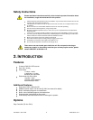
Intimidator™ Scan LED 6 2009-06-04/10:14
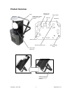
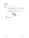
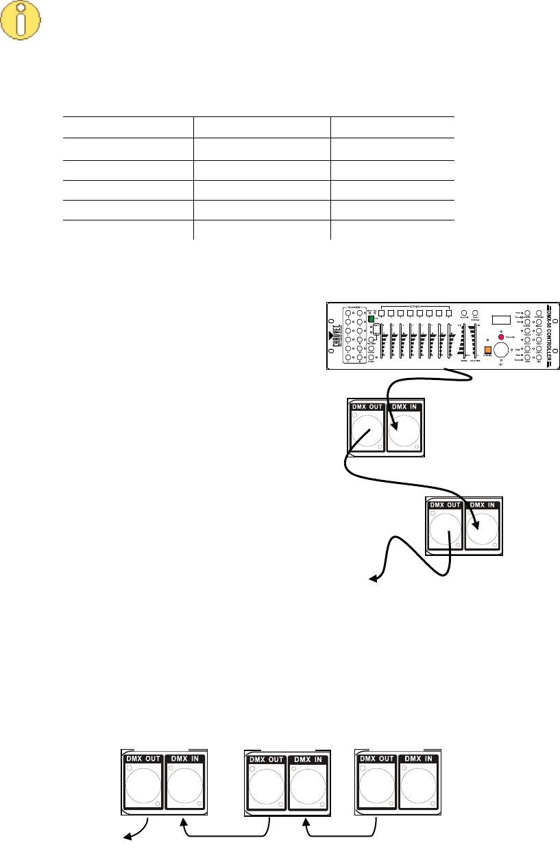
This drawing provides
a general illustration of
the DMX Input/output
panel of a lighting
fixture.
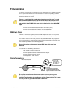
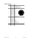
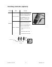
Universal DMX Controller
Continue the link
Master
Slave
Slave
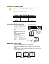
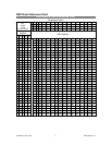
3-Pin to 5-Pin Conversion Chart
If you use a controller with a 5-pin DMX output connector, you will need to use a 5-
pin to 3-pin adapter like the CHAUVET Model No. DMX5M.
The chart below shows a proper cable conversion.
3-PIN TO 5-PIN CONVERSION CHART
Conductor
3-Pin Female (output)
5-Pin Male (Input)
Ground/Shield
Pin 1
Pin 1
Data ( - ) signal
Pin 2
Pin 2
Data ( + ) signal
Pin 3
Pin 3
Not used
Pin 4
Not used
Pin 5
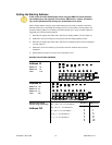
Setting up a DMX Serial Data Link
1) Connect the (male) 3-pin connector of the
DMX cable to the output (female) 3-pin
connector of the controller.
2) Connect the other end of the cable to the
(male) 3-pin input connector of the first
fixture
3) Connect the cable from the output of the
first fixture to the input of the second
fixture.
4) Continue connecting the other features
as indicated above.
CHAUVET Certified DMX Data Cables
Order Code Description
DMX1.5 DMX Cable 1.5 m/4.9 ft
DMX4.5 DMX Cable 4.5 m/14.8 ft
DMX10 DMX Cable 10 m/32.8 ft
Master/Slave Fixture Linking
1) Link the fixtures as indicated in steps 1 to 4 of the previous section.
2) The Master/Slave mode of the fixture does not require any setup or initialization. The first fixture
in the daisy chain automatically assumes the role of Master unit regardless of its DIP switch
settings.
3) Similarly, the fixtures that follow in the daisy chain automatically assume the role of Slave units,
regardless their DIP switch settings.