


Intimidator™ Scan LED 5 2009-06-04/10:14
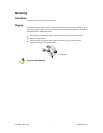
Fixture Linking
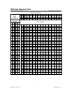
You will need a serial data link to run light shows of one or more fixtures using a DMX-512 controller
or to run synchronized shows on two or more fixtures set to a master/slave operating mode. The
combined number of channels required by all the fixtures on a serial data link determines the number
of fixtures the data link can support.
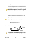
Fixtures on a serial data link must be daisy chained in one single line. To comply
with the EIA-485 standard no more than 32 devices should be connected on one
data link. Connecting more than 32 fixtures on one serial data link without the use
of an optically isolated DMX splitter may result in deterioration of the digital DMX
signal.
Maximum recommended serial data link distance: 500 meters (1640 ft.)
Maximum recommended number of fixtures on a serial data link: 32
DMX Data Cable
To link two or more fixtures together you must use DMX compliant data cables. You can purchase
CHAUVET certified DMX cables directly from a dealer/distributor or construct your own cable.
If you choose to create your own cable, please use data-grade cables that can carry a high quality
signal and are less prone to electromagnetic interference. Use a Belden© 9841 or equivalent cable,
which meets the specifications for EIA RS-485 applications.
Standard microphone cables cannot transmit DMX data reliably over long
distances.
The cable must have the following characteristics:
Type: shielded, 2-conductor twisted pair
Maximum capacitance between conductors: 30 pF/ft.
Maximum capacitance between conductor and shield: 55 pF/ft.
Maximum resistance: 20 ohms / 1000 ft.
Nominal impedance: 100 – 140 ohms
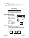
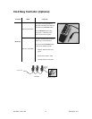
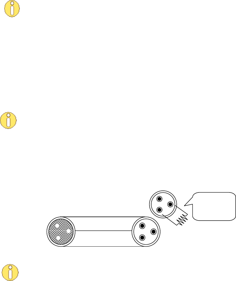
Cable Connectors
Do not allow contact between the common and the fixture’s chassis ground.
Grounding the common can cause a ground loop, and your fixture may perform
erratically. Test the cables with an ohmmeter to verify correct polarity and to make
sure the pins are not grounded or shorted to each other.
COMMON
DMX +
DMX -
INPUT
OUTPUT
1
3
2
1
3
2
1
3
2
120 ohm ¼ W
resistor between
pin 2 (DMX -) and
pin 3 (DMX +) of
the last fixture.
To avoid signal transmission
problems and interference, it is
always advisable to connect a DMX
signal terminator.
DMX connector configuration