


9
HANOVER
™
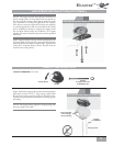
No Light Cap
Adapter Plate
Switch Housing
Cap
Finial
Switch Housing
Mounting Plate
Screws
Finial
Glass Shade
Switch Housing
Mounting Plate
Screws
Socket Plate
Lightbulbs
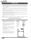
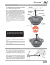
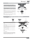
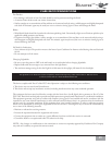
OPTIONAL LIGHT KIT INSTALLATION
Step 11d. Install the third screw and securely tighten all three
screws by hand only using the provided screwdriver.
Note: If you are not installing the optional light kit proceed
to step 12. If you are installing the light kit, proceed to step
13.
Installing the No Light Cap
Step 12a. Using Pack F and the screwdriver provided; install
each of the 3 screws into the switch housing mounting plate,
as shown.
Step 12b. Align the keyhole slots in the cap adaptor plate with
the three screws in the switch housing mounting plate and turn
counterclockwise to align the keyhole slots with the three screws.
Securely tighten all three screws, by hand only.
Step 12c. Remove the fi nial from the no-light cap adaptor
plate.
Step 12d. Install switch housing cap. read fi nial onto threaded
rod of cap adapter plate and tighten securely.
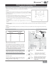
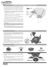
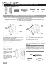
Step 13a. Using pack “E” and screwdriver provided; install
three screws into the Light Assembly Adapter Plate, as
shown.
Step 13b. Connect the Light Assembly connector to the
motor connector.
Step 13c. Carefully tuck the wires and align the keyhole
slots in the Light Assembly with the three screws in the
adaptor plate. Turn counterclockwise to align the keyhole
slots with the three screws.
Step 13d. Securely tighten all three screws by hand only.
Install Incandescent Bulbs
Step 14. Screw in two 60-watt B-10 Candelabra-base
bulbs.
Glass Installation
Step 15. Remove the fi nial from the No-Light Cap Adaptor
Plate. Insert the threaded rod from the Light Assembly
through the hole in the glass shade, as shown. Twist the
fi nial onto the threaded rod. Tighten securely.
SWITCH HOUSING INSTALLATION (CONT.)
Socket Plate
Glass Shade
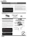
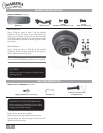
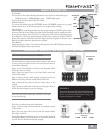
LIGHT KIT HARDWARE (not to scale)
60-watt B-10 bulb
(Candelabra-base)