


8
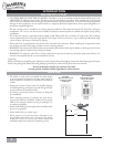
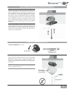
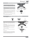
Step 9. Attach the fan wires to the ceiling fi xture outlet box
wiring by placing the bare ends of the wires side by side and
then securing with a wire nut. Test that the connection is
secure by pulling on the wire nut. Connect in this order:
• GREEN leads from mounting plate and downrod
assembly of fan to GROUND conductor of power
source. Secure with wire nut.
• WHITE wire from fan to white NEUTRAL wire in
ceiling fi xture outlet box. Secure with wire nut.
• BLACK power wire from fan to black POWER wire
in ceiling outlet box. Secure with wire nut.
After making the wire connections, the wires should
be spread apart with the grounded conductor and the
equipment-grounding conductor on one side of the outlet
box and the ungrounded conductor on the other side of
the outlet box.
NOTE: If the color of your ceiling wires diff ers from that
described, consult an electrician.
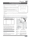
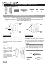
CANOPY ELECTRICAL CONNECTIONS
Step 10a. Tuck the wires into the canopy with the wire nuts
pointed upwards, so that the WHITE and BLACK wires
are on opposite sides of the canopy and all wires are clear
of the canopy opening.
Step 10b. Install canopy hatch with the last canopy screw
and lock washer using the provided screwdriver. To do this,
tilt the fan body away from the hatch opening. Tighten
the screws fi rmly.
Step 10c. Straighten the fan, then check to ensure that there
is no movement between the canopy and the ceiling or the
Perma•Lock
™
downrod and the ball assembly.
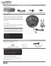
CANOPY HATCH INSTALLATION
Wire Nut
2 Black
Wires
2 White
Wires
3 Green
Wires
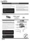
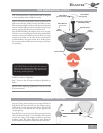
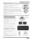
SWITCH HOUSING INSTALLATION
SWITCH HOUSING HARDWARE (not to scale)
Switch Housing
Mounting Plate
Switch Housing
Mounting Plate
No Light Cap
Adapter Plate
Switch Housing
Cap
Motor Housing
Screws
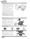
Step 11a. Using screws from Pack E and the provided
screwdriver, install two screws into the motor bottom housing
as shown.
Step 11b. Route the light connector wires through the switch
housing mounting plate as shown.
Step 11c. Align the switch housing mounting plate with
the two screws in the motor bottom housing and turn
counterclockwise to align the keyhole slots in the plate with
the two screws as shown.
Pack E:
Motor & Switch Hous-
ing Mounting Plate
Screws (6)