Section 3. TLX106 Instrumentation Installation
3-6
If you received a telecommunications kit separate from the TLX106 Enclosure,
follow the "Internal Installation" procedures outlined below.
3.3.1 Phone Modems
Phone modems enable communications between the TLX106 Enclosure and a
Hayes compatible modem in your PC over a dedicated phone line. Phone line
surge protection in built into the TLX106 Enclosure.
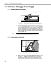
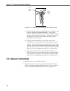
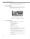
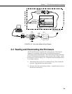
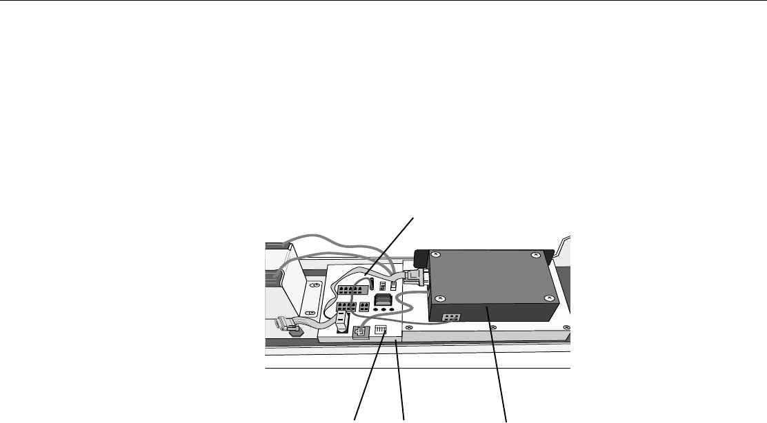
FIGURE 3.3-1. Phone Modem Mounting and Connections
3.3.1.1 Internal Installation
For installation inside the TLX106 Enclosure, the following components are
provided in the phone modem kit:
(1) COM200 or COM300 Phone Modem
(1) 12 inch RJ-11 Patch Cord
(1) Mounting Bracket
(4) Screws
(1) 12 inch 14 AWG Ground Wire
Install the phone modem as shown in Figure 3.3-1.
1. Attach the modem to the modem bracket with the 4 screws provided.
Mount the modem and bracket into the TLX106 Enclosure with the 3 pre-
threaded screws on the mounting plate.
2. Connect the modem 9-pin port to the TLX106 Enclosure port with the
P/N 10588 ribbon cable supplied with the TLX106 Enclosure.
3. Connect the modem RJ-ll jack to the TLX106 Enclosure RJ-11 jack with
the RJ-ll patch cord.
4. Connect the modem ground port to the TLX106 Enclosure ground with
the 14 AWG ground wire.
P/N 10588 Cable
RJ11 Patch
Cord
Ground
Wire
Modem


