


ASSEMBLY
PT5 09/10 Assembly Section 3-2
© 2010 Alamo Group Inc.
ASSEMBLY
TRACTOR SELECTION
The PT5 is specifically designed to be fitted to all tractors with Category I linkage facility and a minimum weight
inclusive of ballast to manufacturer’s specifications of 650 kg (1430 lbs.). The tractor should also be equipped
with an OPEN CENTER HYDRAULIC SYSTEM.
Check chains/stabilizer bars must be available to hold the machine firmly in position during transport and
operation. The tractor selected must have a relief valve setting between 2000 PSI (140 Bar) and 3000 PSI (210
Bar).
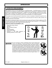
Ballast Weight
Irrespective of the size of the tractor it must be stable while operating the PT5 under all conditions. Due regard
must be paid to operating on slopes and front end ballast as well as rear wheel weights to counterbalance the
overhang of the cutterbar should be added as appropriate.
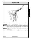
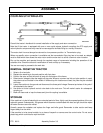
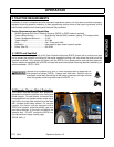
ATTACHMENT TO TRACTOR
1. Unbolt the upper halves of the yoke and fit them on either side of the tractor’s top hitch bracket with the 3/
4” UNF nut and bolt provided. If the tractor has only one top hitch position the bolt will replace the existing
top hitch pin. If more than one location is available, mount the yokes through an alternative position as it
will make it easier to put the machine on and take it off the tractor.
2. Do not tighten the nut at this stage.
3. Attach the machine to the three-point linkage and raise to give 200-250 MM (8”-10”) clearance under the
lowest part of the frame.
4. Rebolt the yoke halves together. It may be necessary to raise or lower the machine on the linkage to
achieve hole alignment. Adjust the top link until the main frame is vertical.
5. Tighten the nut and bolt securing the upper yoke just enough to eliminate any sideways movement. Do not
overtighten and squeeze the top hitch brackets.
6. Tighten the check chains/stabilizer bars.
7. Release its holding chain and position the control valve to suit the tractor and operator. This is achieved by
a combination of height adjustments in the mounting bar attachment and by bending the mounting bar
itself.
8. Turn the parking leg upside down and pin in position.