


7
NOTE
Due to the many variations in tractor / imple-
ment hitch points and corresponding differ-
ences in distances between tractor PTO
shafts and implement input shafts, drivelines
may need to be shortened as described in the
following steps:
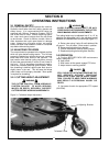
SECTION II
PREPARATION FOR USE
2-1 ATTACHING TO TRACTOR
NEVER STAND BETWEEN TRACTOR AND
CUTTER WHILE TRACTOR IS BEING BACKED
TO HITCH.
ADDITIONAL TRACTOR FRONT BALLAST
MAY BE NEEDED FOR STABLE OPERATION
AND TRANSPORT OF THE 3-POINT HITCH
MOUNTED CUTTER. SEE TRACTOR OPERA-
TOR’S MANUAL FOR RECOMMENDED
WEIGHTS.
DO NOT USE PTO SHAFT ADAPTERS TO
CHANGE SIZE OF TRACTOR PTO SHAFT.
THE CORRECT DRIVELINE MUST BE USED
TO MATCH TRACTOR PTO SHAFT.
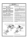
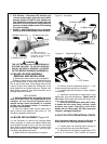
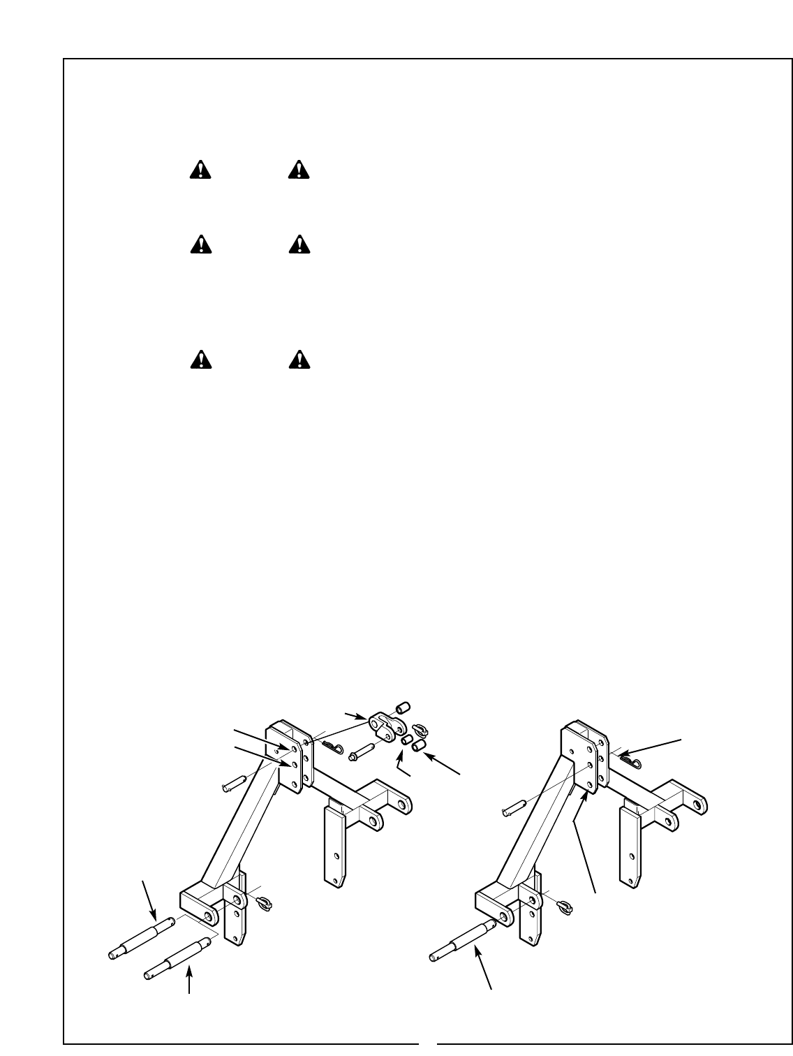
A. Arrange hitch pins, flexible link and bushings
on heavy duty hitches as shown in Figures 2-1 and
2-2 depending on your tractor and hitch type.
Regular standard duty hitches need no adjustment.
B. Attach cutter to tractor 3-point hitch per tractor
operator’s manual. Do not attach driveline at this time.
C. Raise 3-point hitch until front of cutter is approxi-
mately 1-2 inches (25-51mm) lower than rear for
standard cut or until front of cutter is 1 inch (35mm)
WARNING
WARNING
WARNING
D. Raise and lower cutter to determine position
with shortest distance between the tractor PTO shaft
and gearbox input shaft. Shut down tractor leaving
cutter in position of shortest distance. Securely
block cutter in position.
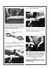
E. Pull driveline apart. Attach outer (female) sec-
tion to tractor PTO shaft. Pull on driveline section to
be sure that yoke locks into place.
F. Hold driveline sections parallel to each other to
determine if too long. Each section should end
approximately 3 inches (76mm) short of reaching
universal joint shield on opposite section. If too
long, measure 3 inches (76mm) back from universal
joint shield and mark on opposite section. (Figure 2-
3). Do this for both sections.
G. Raise and lower cutter to determine position
with greatest distance between PTO shaft and gear-
box input shaft. Shut down tractor leaving cutter in
position of greatest distance. Securely block cut-
ter in position.
higher than rear for extra shredding. Shut down
tractor. Securely block cutter in position. For further
explanation of cutter adjustment, see paragraph 3-2.
Figure 2-1 Cat. II & III Heavy Duty Hitch Figure 2-2 Cat. II & III Heavy Duty Quick Hitch
Cat. III Position
Cat. II Position
Cat. II, Cat. III
Bushings
Cat. III
Cat. II
Cat. III Quick
Hitch Position
Cat. II Quick Hitch Position
Cat. II or III Quick Hitch Position
Flexible Link