


11
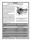
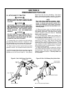
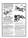
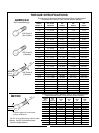
Figure 4-1 Lubrication
(3) Before Each Use
(2) Before Each Use
(6) Before Each Use
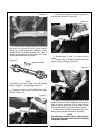
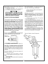
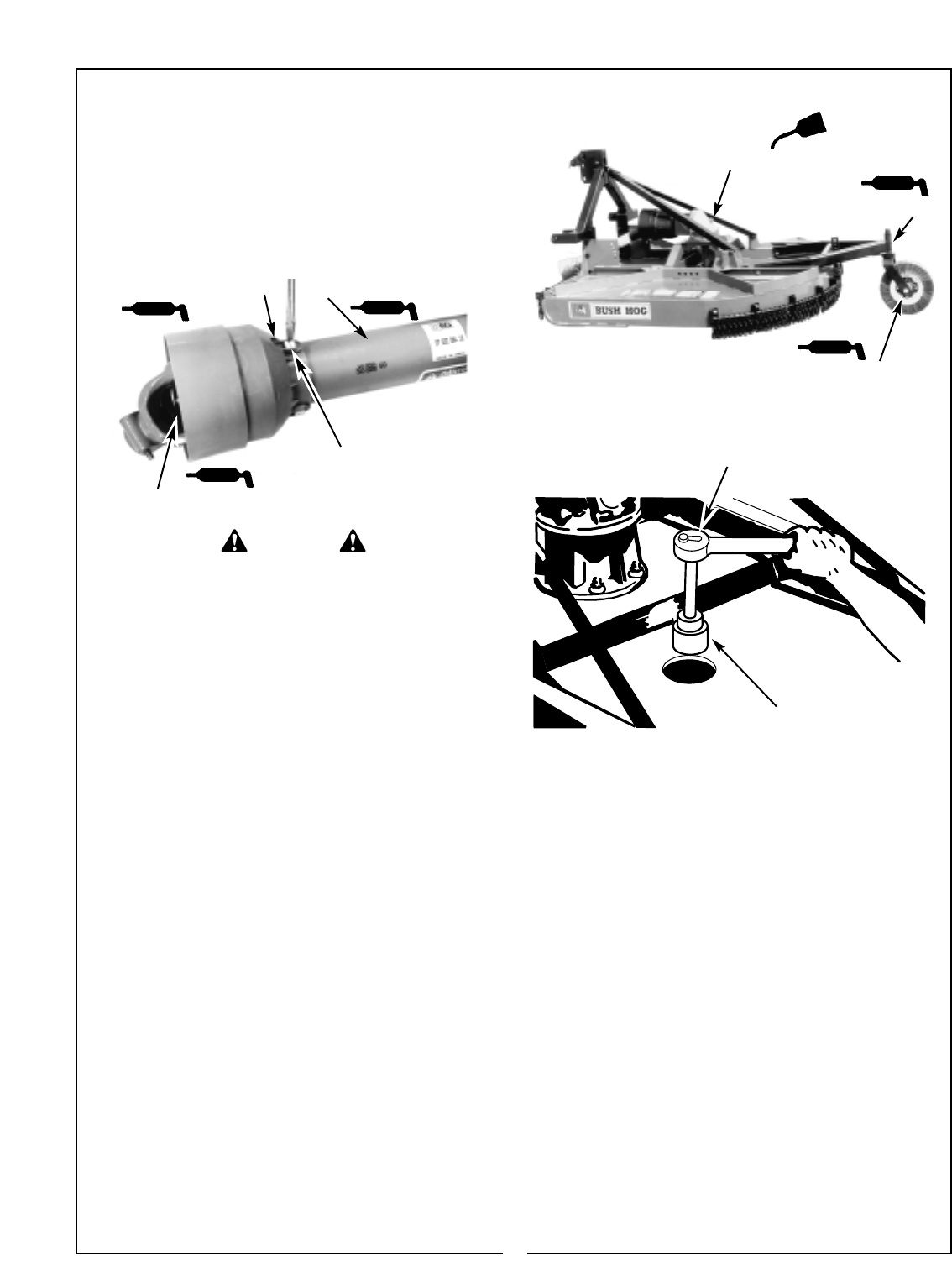
4-4 BLADE REPLACEMENT (Figure 4-2)
It is not necessary to remove the complete blade
holder assembly to replace the blades. Blade bolts
are accessible through a hole in the top of the cutter
deck. Always replace both blades on a spindle using
two blades having the same weight. Use only gen-
uine Bush Hog replacement parts.
A. Raise cutter and securely block in position.
Figure 4-2 Blade Nut Removal
5. PTO Driveline - Disconnect PTO driveline, pull
the two sections apart, apply thin coat of multi-
purpose grease to inside of outer (female) sec
tion. Reassemble sections and install. Pull each
section to be sure driveline and shields are
securely connected. Make certain PTO shielding
is in good condition.
6. Gearbox - Add EP80W-90 gear oil as necessary
to bring oil level to check plug on top of housing.
THE CUTTER CAN FALL FROM HYDRAULIC
SYSTEM FAILURE. TO AVOID SERIOUS
INJURY OR DEATH, SECURELY SUPPORT
CUTTER BEFORE WORKING UNDERNEATH.
WARNING
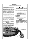
4-3 BLADE HOLDER ASSEMBLY
REMOVAL AND INSTALLATION
A. Remove the lower shaft nut and lockwasher.
B.Wearing heavy gloves, grasp blade holder and
pull off tapered shaft. If stuck, align bolt with access
hole in top of cutter deck. Using sledge hammer and
a piece of pipe, strike blade bar. Rotate pan to the
other blade bolt and strike blade bar. Repeat until
blade holder comes off. Care should be taken not to
damage blade bolt threads.
REPLACEMENT
A. Replace blade holder and tighten the lower
shaft nut to 600 ft./lbs. If a torque wrench is not
available, the nut should be tightened with a
wrench having a three foot handle, or a section
of pipe over the wrench handle, if a wrench of
this size is not available.
B. Strike the blade holder several times with a
heavy hammer and retighten lower shaft nut. This
should be repeated several times.
D. Assemble new blades to blade holder using
blade bolts, nuts and lockwashers. Tighten nuts to
450 ft./lbs. Strike blade bolt head with heavy ham-
mer to seat, then retighten.
E. Check to be sure blades swing 360° freely.
If blades will not swing freely, remove, locate
problem, and repair. Operating cutter when
blades will not swing freely will cause excessive
vibration, damaging implement.
4-5 SLIP CLUTCH OPERATIONAL CHECK
After implement had been stored for 30 days or
more, perform the following operational check:
A. Loosen eight nuts retaining clutch springs 1/3
turn or until spring can be turned with fingers.
B. With tractor at idle speed, engage tractor PTO
drive for 2-3 seconds. Clutch should slip without
(4) Before Each Use
(5) Before Each Use
(1) Before Each Use
1-11/16” Socket
B. Remove nuts from blade bolts using a 1-11/16”
socket through the access hole in the deck.
C. Inspect blade bolt shoulder for wear. Replace
if necessary.
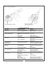
To remove yoke shield:
Turn slotted head 90° with
screwdriver, remove turn screw
and slide cover back.