


SECTION V
ASSEMBLY
IMPORTANT
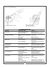
Tighten all fasteners to specifications on Torque
Chart unless otherwise indicated.
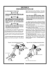
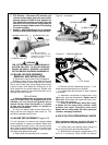
5-1 STANDARD 3-POINT HITCH (Figure 5-1)
To attach a standard duty hitch to your cutter:
Remove the lift pins and all bolts from the hitch.
Install the A-frame struts of the assembly between
the mounting brackets on the base frame. Extend
the 3-point hitch yoke between the A-frame and the
brackets at the rear of the machine and bolt into
place. Replace lift pins and bolts at bottom of A-
frame struts, then tighten all bolts and lift pins
securely.
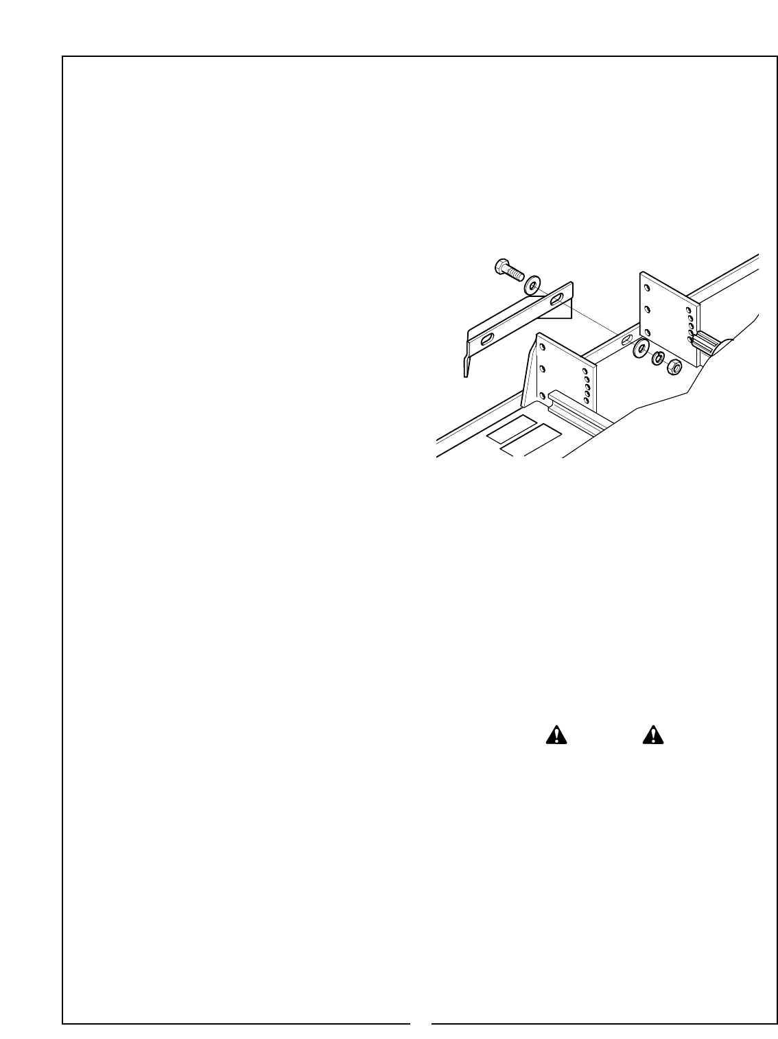
5-2 HEAVY DUTY 3-POINT HITCH
To attach a heavy duty hitch to your cutter:
Remove the bolts from the hitch. Install the mast
weldment between the mounting brackets on the
base frame. Extend the 3-point hitch yoke between
the top of the mast to the brackets at the rear of the
machine and bolt into place. Fasten the mast to the
deck brackets using 7/8 x 2-1/2” bolts, lockwashers
and nuts in the top holes and 5/8 x 2” bolts, lock-
washers and nuts in the bottom holes. Tighten all
bolts. Arrange the lift pins and flexible link according
to your tractor’s requirements. Refer to Figure 2-1.
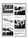
5-3 TAILWHEEL ASSEMBLY
Connect your cutter to the tractor and lift it high
enough for the caster wheel assembly to clear the
ground. Install the tailwheel frame as shown. Insert
the caster fork up through the pivot tube. Fasten in
place with lock collar and roll pin. To adjust to
desired cutting height, bolt end of adjusting bracket
to lugs on base frame and fasten other end to tail-
wheel bracket using the desired adjusting hole.
Tighten all bolts securely.
5-4 GEARBOX INPUT SHIELD
Remove four existing bolts from around input
shaft in front of gearbox. Fasten metal shield bracket
to gearbox using these bolts. Fasten plastic shield
(with access opening to the top) to the shield bracket
using four 5/16 x 3/4” bolts, flatwashers, lockwash-
ers and nuts.
5-5 FRONT CHAIN GUARDS (Standard) &
REAR CHAIN GUARDS (Optional)
Position chain assembles against mainframe as
shown and fasten with 1/2 x 1-1/2” bolts, flatwash-
ers, lockwashers and nuts. (Figure 5-1)
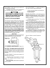
5-7 DRIVELINE INSTALLATION
(Slip Clutch Optional)
A. Remove pivot bolt from spline end of clutch.
Remove inspection cover from clutch shield.
B. Slide clutch onto gearbox input shaft aligning
bolt holes with slot in input shaft. Fasten with clamp
bolts, lockwashers and nuts. Torque to 30 ft./lbs.
C. Loosen eight nuts retaining clutch springs
1/3 turn or until spring can be turned with fingers.
D. With tractor at idle speed, engage tractor
PTO drive 2-3 seconds. Clutch should slip with-
out turning blades.
E. Retighten nuts to original position. If adjust-
ment is necessary, refer to Section 4-6.
OVER-TIGHTENING SPRING NUTS MAY
CAUSE DAMAGE TO IMPLEMENT AND/OR
TRACTOR DUE TO INCORRECT SLIP
CLUTCH TORQUE SETTING. ALWAYS
FOLLOW THE PROPER ADJUSTMENT PRO-
CEDURE.
IMPORTANT
Before operation,fill gearbox with EP80W-90
gear oil to check plug on rear of gearbox. Allow
time for oil to seep through bearings into lower
housing, then recheck oil level. Insure that vent
hole in fill plug is open to allow pressure to
escape from gearbox during operation.
WARNING
15
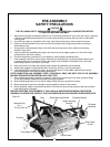
5-6 FRONT GUARD ASSEMBLY (Optional)
Fasten guard to center front of mainframe
using1/2 x 1-1/2” bolts, flatwashers, lockwashers
and nuts.
Figure 5-2 Front Guard