


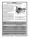
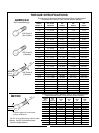


Figure 4-3
Spring Length
turning blades. If clutch does not slip, contact your
authorized Bush Hog dealer.
C. Retighten nuts to within 1/64” of original posi-
tion. Initial spring length is shown in Figure 4-3.
4-6 SLIP CLUTCH ADJUSTMENT
The slip clutch is factory preset to the correct torque
for protecting implement and tractor. Periodic
adjustment is recommended; refer to section 4-5.
Should adjustment be needed, first check to be sure
all spring lengths are the same. Initial spring length
is shown in Figure 4-3. If necessary, adjust nut on
any spring that is unequal. Adjust all eight spring
retaining nuts 1/3 of a turn (2 flats on a nut) and
check clutch slippage. If further adjustment is neces-
sary, do so in 1/3 turn increments. Adjust only to
provide sufficient torque to prevent slippage under
normal conditions. Occasional slippage is normal
for drivetrain protection. If satisfactory results cannot
be obtained, consult your Bush Hog dealer.
IMPORTANT
Do not overtighten nut and cause spring to
become solid as this will cause shaft to fail.
WARNING
OVERTIGHTENING SPRING NUTS MAY
CAUSE DAMAGE TO IMPLEMENT AND/OR
TRACTOR DUE TO INCORRECT SLIP CLUTCH
TORQUE SETTING. ALWAYS FOLLOW THE
PROPER ADJUSTMENT PROCEDURE.
1-17/64”
32.2 mm
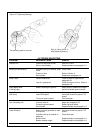
4-7 GEARBOX MAINTENANCE (Figure 4-4)
OIL LEVEL - The gearbox assembly on the 305/306
rotary cutters are shipped from the factory less oil.
Use EP80-90 gear oil and fill to the plug located on
the top of the gearbox. Never fill the gear- box above
this level. Seals could become damaged due to
expansion.
OIL SEAL LEAKAGE - The three main causes of oil
seal failure are as follows:
1. Operating cutter for any length of time with
wire or litter wrapped around the upper or lower
shaft.
2. Loose bearings.
3.Worn seals. Leaky seals should be replaced as
soon as possible.
SEAL REPLACEMENT - To replace the seals on
your cutter, follow the steps outlined below:
1. Remove the blade holder and universal joint.
2. Knock out old seals.
3. Install new seals.
BEARING ADJUSTMENT - Loose bearings can be
detected by applying pressure in an “in and out”
direction on the upper and lower shafts to check for
end play. To tighten the bearings, the following pro-
cedure may be used.:
1. Remove upper end housing. This provides
access to both adjusting nuts.
2. If your gearbox is an earlier model with a lock-
washer and a grooved adjusting nut, the lock must
be bent out of the groove of the adjusting nut before
adjustments can be made. In later models there is a
roll pin holding the nut in place. When bearings are
to be adjusted, either due to years of operation or
due to replacement of gears, shaft, or bearing, the
nut must be split using a cold chisel and a new nut
must be used. (Figures 4-4 & 4-5)
3. Tighten the adjusting nuts until slack is taken
up. IMPORTANT: The gears are pressed on, and
this could cause the adjusting nut to appear tight
when there is still slackness in the bearings.
Figure 4-4 Gearbox Internal Components
Adjusting Nuts
Seal
Seal
12