


9
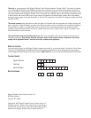
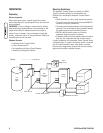
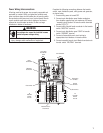
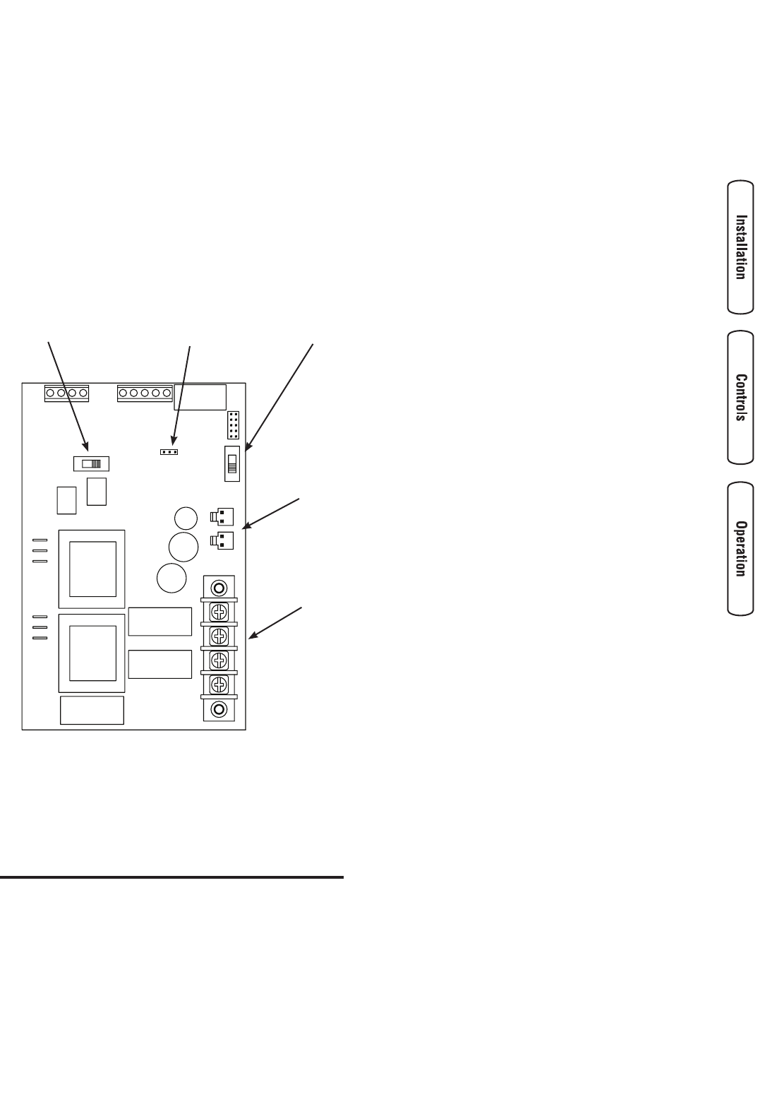
System Setup
You must perform the following before operating the system:
• If generator is installed in an area regularly subjected
to temperatures below 40°F (4°C), select a 50 second
warm up time by moving jumper installed on JP2 from
‘20’ position to ‘50’ position.
• Place the 2 position sliding switch on the control
module in the NG or LP position, whichever is
appropriate for your system.
• Place the 3 position sliding switch on the control
module to match the KW rating of the Home Standby
Generator set.
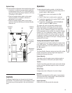
Controls
The Manual Override lever is to be used only by licensed
professionals. The essential branch circuit breakers are used
in the same way as those supplied in the main distribution
panel.
Operation
To select automatic transfer operation, do the following:
1. Set essential circuit breaker that sends utility power to
transfer switch to “On” position.
2. Set generator’s main circuit breaker to its “On”
position.
3. Install 15 Amp fuse in control panel on generator.
4A. If generator is equipped with a system ON/OFF switch,
set switch to “ON” position.
B. If generator is equipped with a AUTO/OFF/MANUAL
switch, set switch to “AUTO” position.
The system will now be in automatic operation mode.
When the generator is providing power to the transfer
switch, the controller is constantly monitoring generator
power. If the air conditioner is called to run, and there is
sufficient generator power available, the controller will close
contacts “A-A” to air conditioner contactor. Contacts “B-B”
will open before contacts A-A close. If loads are too great
for generator, contacts A-A and/or B-B will open. When air
conditioning is not needed, A-A will open. If enough power is
available, B-B will close.
Testing the Automatic Transfer Switch
Turn the essential circuit breaker feeding the transfer switch
to the “Off” position. The automatic sequence will follow. To
go back to utility power, turn the essential circuit breaker to
the “On” position.
Utility Fail
The Home Standby Generator set senses when utility voltage
is below 70 percent of nominal. Engine start sequence is
initiated after 6 second time delay.
Engine Warm-Up
Time delay to allow for engine warm-up before transfer is
fixed at 20 seconds or 50 seconds (see System Setup).
Transfer
Transfer from utility to generator supply occurs after voltage
is above set levels. Minimum engine run time is 5 minutes
after transfer.
Utility Pickup
Voltage pickup level is 80 percent of nominal voltage.
Retransfer
Retransfer from generator to utility supply is approximately
10 seconds after utility voltage supply is above pickup level
and minimum run time is completed.
Engine Cool Down
Engine will run for 60 seconds after retransfer.
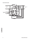
JP2
2 Position
Switch
3 Position
Switch
CT1 & CT2
Connectors
Supervisory
Contacts