


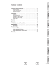

5
Introduction
Your Briggs & Stratton Transfer Switch is supplied with this
combined “Installation and Operator’s Manual”. This is an
important document and should be retained by the owner
after the installation has been completed.
Every effort has been expended to make sure that the
information in this manual is both accurate and current.
However, the manufacturer reserves the right to change,
alter or otherwise improve the system at any time without
prior notice.
For the Home Owner
To help you make informed choices and communicate
effectively with your installation contractor(s),
Read and understand the Owner Orientation Section
of this manual BEFORE contracting or starting your
transfer switch installation.
To arrange for proper installation, contact the store at which
you purchased your Briggs & Stratton Transfer Switch, your
dealer, or your utility power provider.
The Transfer Switch Warranty is VOID
unless the system is installed by a
licensed electrical professional.
Owner Orientation
The illustrations are for typical circumstances and are meant
to familiarize you with the installation options available with
your transfer switch.
Local codes, appearance, and distances are the factors that
must be considered when negotiating with an installation
professional. As the distance from the existing electrical
service increases, compensation in wiring materials must
be allowed for. This is necessary to comply with local codes
and overcome electrical voltage drops.
The factors mentioned above will have a direct effect on the
overall price of your transfer switch installation.
NOTE: Your installer must check local codes AND obtain
permits before installing the system.
• Read and follow the instructions given in this manual.
• Follow a regular schedule in caring for and using your
transfer switch, as specified in the manual.
Installer Responsibilities
• Read and observe the safety rules.
• Read and follow the instructions given in this manual.
• Check federal, state and local codes and authority
having jurisdiction, for questions on installation.
• Ensure generator is not overloaded with selected loads.
If you need more information about the transfer switch, call
(800) 743-4115, between 8:00 AM and 5:00 PM CT.
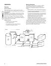
Equipment Description
The transfer switches are intended to transfer essential
circuits of normal residential installations when used with the
supervisory contacts provided. The load is connected either
to utility power (normal) or home standby power (generator).
The transfer switch monitors utility and generator voltages
and will automatically connect essential circuits to the
appropriate source of power.
These switches make it easy for a licensed electrician to
complete a home standby installation. The transfer switch
contains an automatic transfer switch and control circuitry,
and up to 16 essential branch circuit breakers, all in one
enclosure.
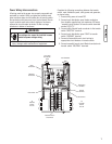
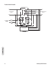
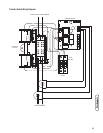
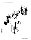
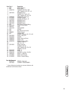
Major components of the transfer switch are a 2 pole
double throw transfer switch, control circuit board, fused
utility terminals, branch circuit breakers and bus, and
interconnecting wiring.
The transfer switch is solenoid-operated from utility or
generator inputs and contain suitable mechanical and
electrical interlock switches to eliminate the possibility of
connecting the utility service to the generator output. It has
ratings capable of switching utility or generator power into
the essential circuits. In addition, a manual override lever is
provided for the transfer function.
The control circuit board has active circuits sensing utility
and generator voltages. It creates a signal for the generator
start-up, switch transfer, retransfer when utility is restored,
and generator cool-down periods. The control board also
contains red and green LED’s indicating the power sources
available and two relay operated contacts that provide
supervisory control of external loads.