


Power Wiring Interconnections
All wiring must be the proper size, properly supported and
protected by conduit. Utility and generator conduits must
enter enclosure above circuit breaker bus in transfer switch.
No conductors shall pass over top of control board. Branch
circuit conduits must enter sides or bottom of enclosure
adjacent to circuit breaker terminals. Do Not use large
knockouts in bottom of enclosure.
WARNING
Low voltage wire cannot be installed in same
conduit as power voltage wiring.
Failure to follow above warning could cause personal
injury, damage and/or malfunction of equipment.
•
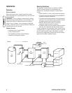
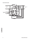
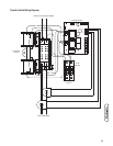
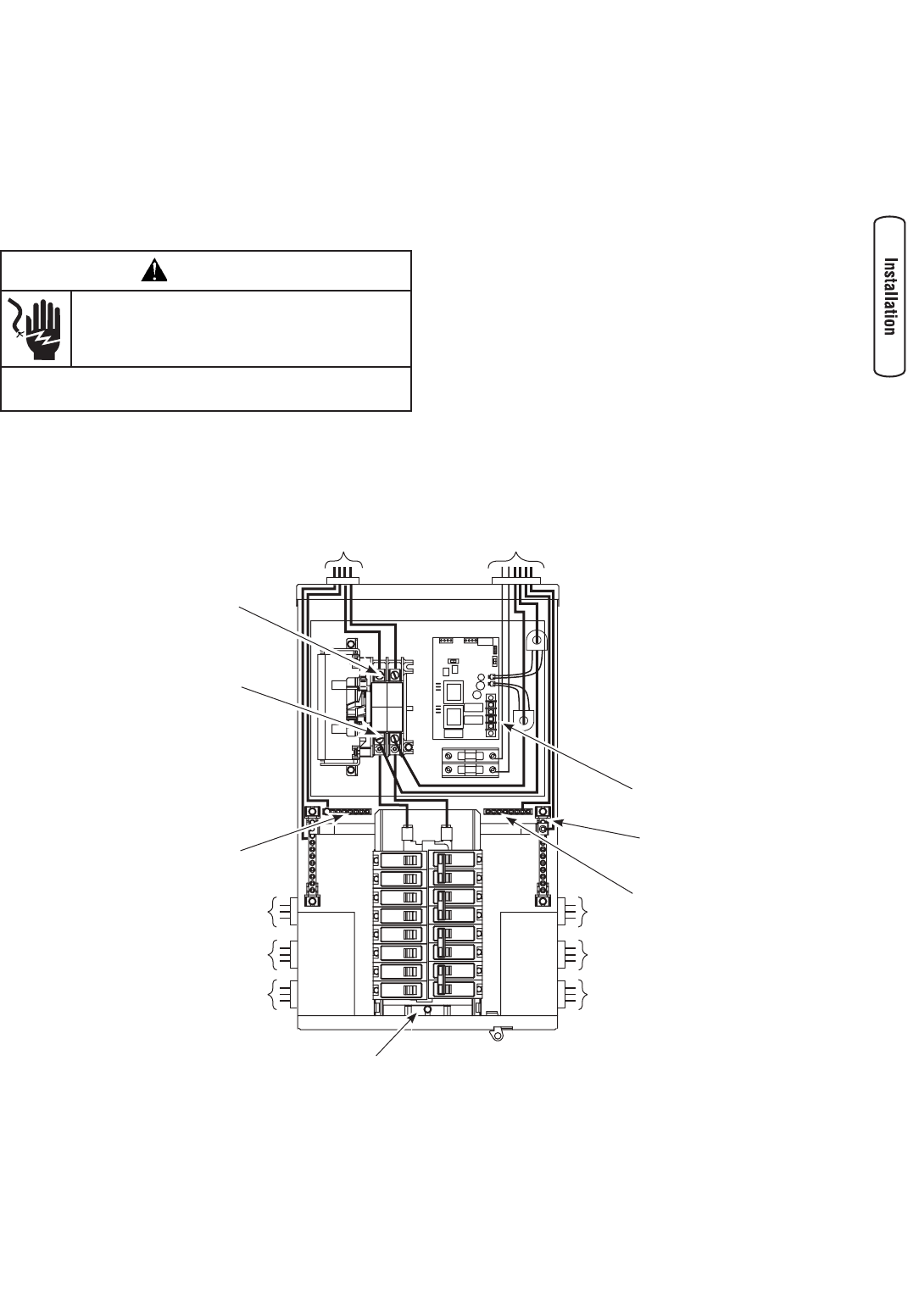
Complete the following connections between the transfer
switch, main distribution panel, utility power and generator,
as shown below.
1. Ensure utility power is turned OFF.
2. Connect main distribution panel feeder conductors
from installer-supplied two pole maximum 100 amps
“essential circuit breaker” to transfer switch terminals
marked “UTILITY”.
3. Connect utility Neutral feeder conductor to the transfer
switch “NEUTRAL” terminal.
4. Connect main distribution panel “GND” to transfer
switch “GROUND” terminal.
5. Connect all essential branch circuit wiring to
appropriate circuit breakers in transfer switch.
6. Connect essential branch circuit Neutral conductors to
transfer switch “NEUTRAL” terminals.
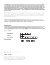
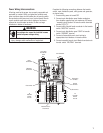
7
Ground Bus
To
Essential
Branch
Circuits
From Generator
Neutral
Terminal
Supervisory
Contacts
From Main
Distribution
Panel
Generator
Connection
Utility
Connection
To
Essential
Branch
Circuits
Ground Bus
Essential Branch
Circuit Buss