


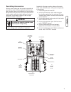
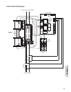
7. Connect generator power supply conductors from the
generator’s control panel to transfer switch terminals
marked “GENERATOR”. Each conductor should pass
through hole of current transformer before making
connection.
8. Connect generator Neutral from the generator control
panel to the transfer switch “NEUTRAL” terminal.
9. Connect generator Ground from the control panel to the
transfer switch “GND” terminal.
10. Plug in current transformer leads into “CT1” and “CT2”
terminals on control module.
NOTE: Assure generator equipment grounding conductor
is connected per applicable federal, state and local codes,
standards and regulations.
11. Connect generator “UTILITY 240 VAC” terminals to
transfer switch “UTILITY 240 VAC” terminals. Use
minimum #14 AWG conductors.
12. Tighten all wire connections/fasteners to proper torque.
See inside transfer switch enclosure for proper torque
values.
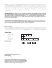
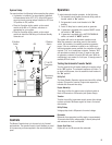
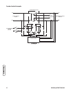
Supervisory Control Wiring
The supervisory control terminal strip on the control module
in the transfer switch has four connections for customer use.
There are two sets of “Normally Closed” contacts available.
They will be activated when generator power is required.
These can be used for supervisory control of large connected
loads on generator. Loads will be allowed to operate if there
is enough generator power available.
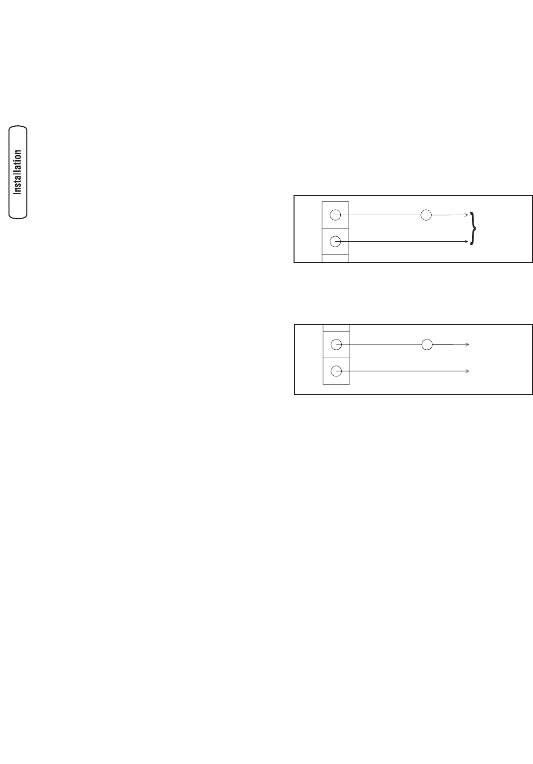
1. Terminals “A-A” on control module are rated for
24 VAC and air conditioner contactor control. Contacts
are connected in series with the air conditioner
contactor control circuit.
2. Terminals “B-B” on control module are rated for 1 Amp
125 VAC and installer supplied contactor to control a
large load. Example: electric hot water heater. Contacts
are connected in series with the contactor control
circuit.
3. Tighten all wire connections/fasteners to proper torque.
See inside transfer switch enclosure for proper torque
values.
8 BRIGGSandSTRATTON.COM
B
B
Contactor
Neutral
120 VAC
A
A
Air Conditioner Contactor
24 VAC