


9
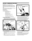
Edger Blade Angle Adjustment
WARNING: Rotating cutting blade may throw
objects causing personal injury. Keep area
clear of bystanders and do not operate
without guards in place.
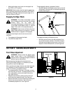
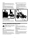
The cutting blade can be adjusted to eight positions. To
adjust the blade angle, proceed as follows:
• Place the blade clutch/depth control lever in the
disengaged position (top notch).
WARNING: Always place the blade clutch/
depth control lever in the DISENGAGED
position before adjusting the blade angle.
• Pull forward on the blade angle adjustment lever
before rotating the spindle assembly.
• Release the blade angle adjustment lever into one
of the notches on the pivot bracket. See Figure 9.
Figure 9
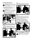
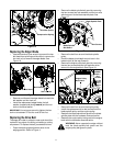
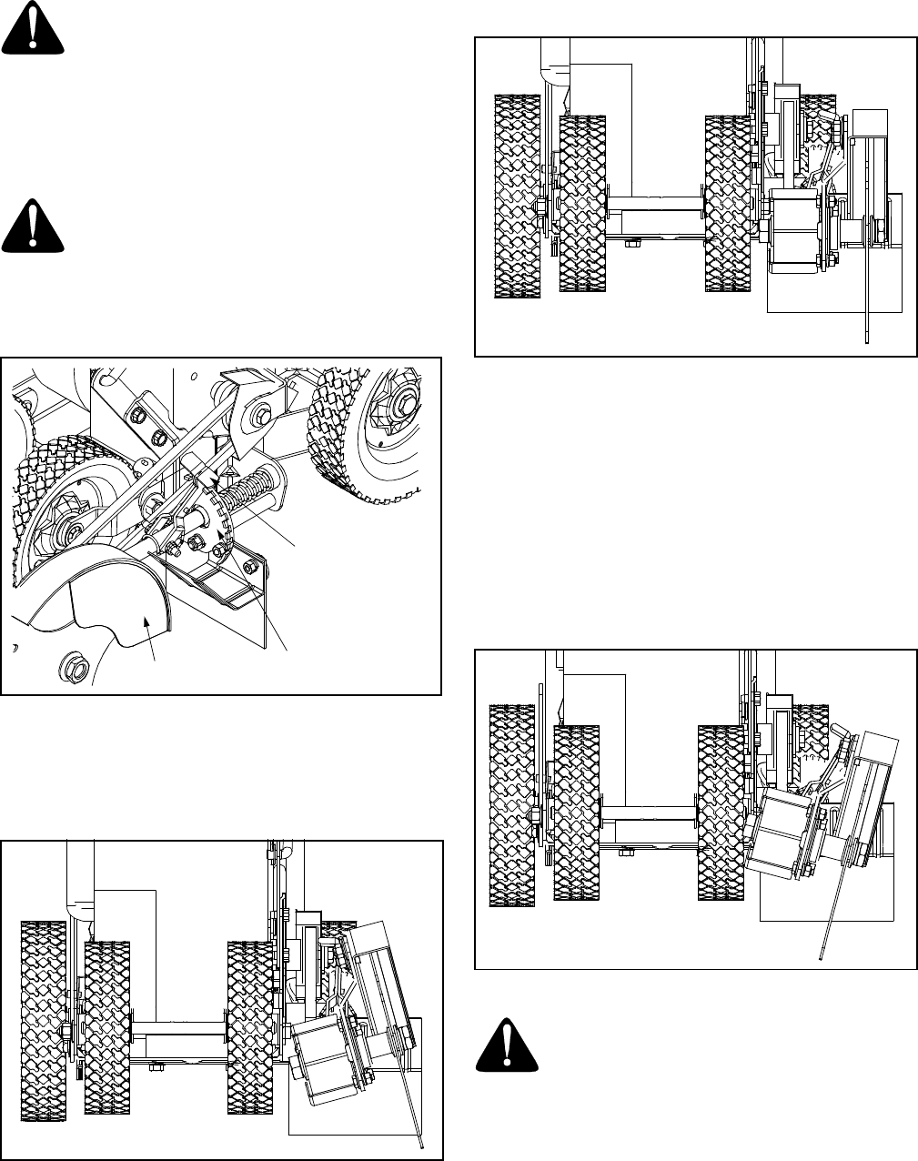
Trenching
Placing the blade angle adjustment lever in the notch
furthest to the right will put the spindle assembly at a
proper angle for trenching with the edger as illustrated
in Figure 10.
Figure 10
Edging
Placing the blade angle adjustment lever in the second
notch from the right will put the spindle assembly at a
90° angle for vertical edging as illustrated in Figure 11.
Figure 11
Beveling
Placing the blade angle adjustment lever in the third,
fourth, fifth, sixth or seventh notch (from the right) will
put the spindle assembly at various angles for beveling
with the edger as illustrated in Figure 12.
IMPORTANT:
When the spindle assembly is rotated
counter-clockwise (putting the blade closer to a
horizontal position), it IS necessary to change the
position of the front, left wheel to prevent the edger
blade from striking the wheel. See Front Wheel Adjustment
earlier in this section.
Figure 12
WARNING: Always place the blade clutch/
depth control lever in the DISENGAGED
position before adjusting the blade angle.
Blade Angle
Adjustment Lever
Pivot Bracket
Spindle Assembly