


8
• Move the throttle control lever on the engine into
the STOP or OFF position.
IMPORTANT:
Make certain that the engine’s spark plug
wire is properly grounded as instructed in SECTION 2:
Assembling The Edger before storing the edger for its
next use. Refer to Figure 2.
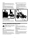
Engaging the Edger Blade
WARNING: The blade clutch/depth control
lever is designed to minimize the risk of blade
contact injury. Do not under any
circumstances attempt to defeat the function
of the blade clutch/depth control, or use the
edger if the control is not adjusted properly.
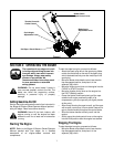
WARNING: Keep hands and feet away from
edger blade whenever the engine is running,
whether blade is engaged or disengaged.
The blade clutch/depth control lever has two main
functions:
1. To engage and disengage the blade.
2. To control the depth of cut.
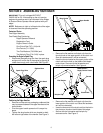
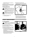
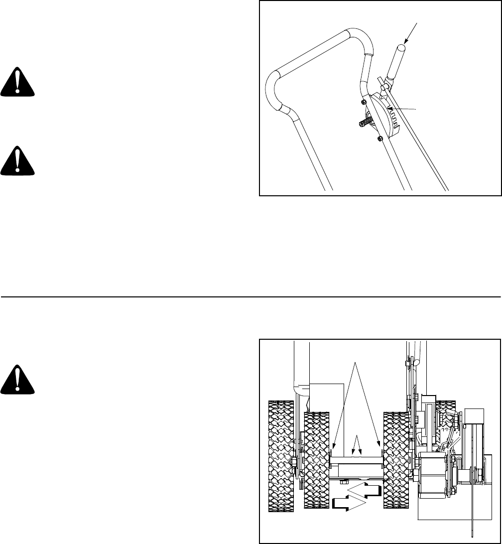
To disengage the blade, proceed as follows:
• Move the blade clutch/depth control lever to the left
and place it in the top notch in the depth adjustment
bracket. See Figure 7.
Figure 7
To engage the blade, proceed as follows:
• Move the control lever to the left and place it into
any of the five lower notches. The further forward
the blade clutch/depth control lever is moved, the
deeper or lower the blade will cut into the ground.
SECTION 5: MAKING ADJUSTMENTS
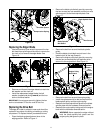
Front Wheel Adjustment
WARNING: Always place the blade clutch/
depth control lever in the DISENGAGED
position and turn the edger’s engine off before
performing any adjustments.
Before operating the edger with the blade in the
trimming (horizontal) position, it is necessary to alter
the position of the front, left wheel.
When operating the edger with the curb wheel lowered,
it is necessary to alter the position of the front, right
wheel. To do either, proceed as follows:
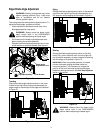
• To change position of the front, left wheel, remove
the hairpin clip on the left. To change position of the
front, right wheel, remove the hairpin clip on the
right. See Figure 8.
• Reposition the wheel by sliding it down the front
axle toward the opposite wheel. See Figure 8.
• Secure the wheel in its new location by inserting the
hairpin clip removed earlier in the hole found
immediately adjacent to it. See Figure 8.
Figure 8
Blade Clutch /
Depth Control Lever
Depth Adjustment
Bracket
Hairpin Clips
Holes