


43
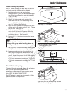
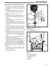
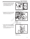
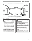
8. Locate the wire harness disconnect points under
the right instrument control panel. Disconnect the
wire harnesses by squeezing the quick release
tabs and pulling the main unit wire harness
connector (B, Figure 61) from the instrument
panel wire harness connector (B).
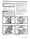
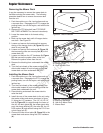
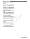
9. There are two (2) 1/2” bolts and washers (A & B,
Figure 62) that secure the operator compartment
(C) to the unit at the front pivots. Loosen and
remove both 1/2” bolts and washers.
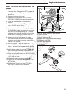
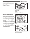
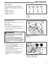
10. Loosen and remove the 3/8 X 2-1/2” bolt, 3/8
washer and 3/8-16 nylock flange nut (A, Figure
63) that secures the shock (B) to the bottom shock
mount (C).
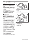
11. The operator compartment can now be removed
from the unit by raising the compartment up and
pulling it backwards from the unit.
Figure 61. Wire Harness
A. Instrument Panel Wire Harness Connector
B. Main Unit Wire Harness Connector
C. Quick Release Tabs
Figure 63. Bottom Shock Mount
A. Shock Hardware
B. Shock
C. Bottom Shock Mount
Figure 62. Operator Compartment Front Pivots
A. 1/2” Bolt
B. Washer
C. Operator Compartment
D. Spacers
E. Rubber Pivot Mounts
C
B
A
B
A
C
E
D
C
C
B
A
Regular Maintenance
Not for
Reproduction