


41
A
B
F
E
D
C
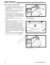
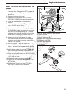
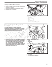
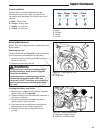
Figure 55. Pusher Rollers
A. 1/2”-13 X 3-1/2” Bolt
B. Deck Guide
C. Sleeve Bushing
D. Roller
E. 1/2 USS Washer
F. 1/2-13 Hex Nylock Flange Nut
Removing the Operator Compartment
Assembly
It may be necessary to remove the operator
compartment assembly to facilitate servicing the unit.
The following procedure details how to remove the
operator compartment assembly from the unit.
1. Park the machine on a flat, level surface such as
a concrete floor. Disengage the PTO, engage the
parking brake, turn off the engine, and remove the
ignition key.
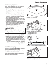
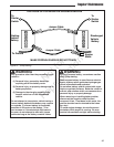
2. Remove the right tank (A, Figure 56) from the unit
by unscrewing the three (3) wing bolts (B) from the
tank and pulling the tank off the unit.
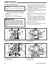
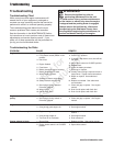
3. Remove the left fuel tank (A, Figure 57) from the
unit by unbolting the three (3) bolts, lock washers
and washers (B) that secure the fuel tank to the
unit. The fuel line is still connected to the fuel
tank. Position the tank so that you can access the
operator compartment pivot hardware, but do not
remove the tank from the unit.
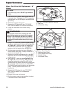
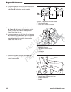
Figure 56. Removing the Tank
A. Tank
B. Wing Bolts
A
A
B
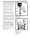
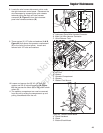
Figure 57. Removing the Fuel Tank
A. Fuel Tank
B. Fuel Tank Mount Hardware
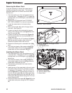
Installing the Mower Deck continued.
6. Install the hanger chains to the deck lift rod pivots
as shown in figure 53.
7. Remove the blocking from underneath the unit.
8. Reinstall the PTO drive belt.
B
Regular Maintenance
Not for
Reproduction