


42
www.ferrisindustries.com
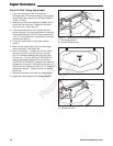
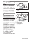
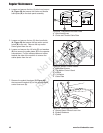
Figure 58. Disconnect the Cable Plate
A. Allen Head Screw
B. Choke and Throttle Cable Plate
A
A
B
4. Loosen and remove the four (4) allen head screws
(A, Figure 58) that secure the choke and throttle
cable plate (B) to the dash panel assembly.
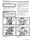
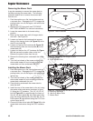
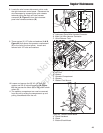
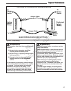
5. Loosen and remove the two (2) allen head bolts
(A, Figure 59) that secure the top motion control
guard (B) to the unit. Remove the top motion
control guard from the unit
6. Loosen and remove the 1/4 bolts (C) and washers
(D) that secure the cable plates (E) to the operator
compartment. Pull the cables plates and cables
towards the side of the machine to remove the
cables plates from the unit.
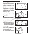
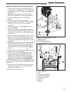
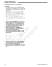
7. Remove the eyebolt hardware (B, Figure 60)
that secures the eyebolt (C) to the ground speed
control lever arm (A).
B
C
A
Figure 60. Removing the Cables
A. Ground Speed Control Lever Arm
B. Eyebolt Hardware
C. Eyebolt
Figure 59. Motion Control Cables
A. Allen Head Screws
B. Top Motion Control Guard
C. 1/4 Bolt
D. 1/4 Washer
E. Cable Plate
C
D
A
B
E
Regular Maintenance
Not for
Reproduction