


5
Component Installation
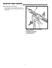
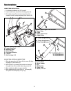
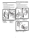
Figure 3. Lower Chute to Boot Installation
A. Latch Pin
B. Carriage Bolt, 1/4-20 x 5/8
C. Locknut, 1/4-20
D. Lower Chute
E. Locknut, Center Lock, 5/16-18
F. Rubber Strap
G. Locknuts, Whiz Lock, 5/16-18
H. Rod, Boot Mount
I. Capscrew, Hex Head, 5/16-18 x 1-1/4
J. Capscrew, Hex Head, Thin, 5/16-18 x 1
D
B
C
F
A
G
G
H
I
J
E
LOWER CHUTE ROD AND PIN INSTALLATION
1. Insert the head of latch pin (A, Figure 3) through front
hole of lower chute (D). Secure with carriage bolt (B)
and locknut (C).
2. Install the rod (H) to lower chute (D) using locknuts
(G) for front holes. Tighten hardware.
3. Install the rubber strap (F) onto capscrew (I) securing
with locknut (E).
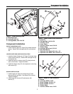
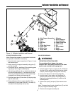
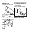
Figure 4. Handle to Tube Installation
A. Handle
B. Locknuts, KEPS, 1/4-20
C. Screw, Slotted, 1/4-20 x 1/2
D. Screw, Slotted, 1/4-20 x 1
E. Rubber Strap
F. Locknut, Center Lock, 1/4-20
HANDLE INSTALLATION
1. Install handle (A, Figure 4) using screw (C) and
locknuts (B) for rear hole. Use screw (D) as shown.
Tighten hardware.
2. Install strap (E) to screw (D) and secure with
locknut (F).
B
D
B
F
A
E
C
Component Installation
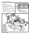
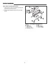
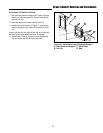
INSTALL MOUNTING PLATE
1. Install mounting plate (A, Figure 2) to mower deck as
shown. Secure with carriage bolts (C) and locknuts
(B).
Figure 2. Install Mounting Plate
A. Mounting Plate
B. Locknuts, 5/16-18
C. Carriage Bolts, 5/16-18 x 5/8
C
B
A