


8
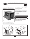
Briggs & Stratton Power Products Home Generator
Installation Manual
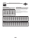
• Piping must be of the correct size to maintain the
required supply pressures and volume flow under varying
generator load conditions with all gas appliances
connected to the fuel system turned on and operating.
• Use an approved pipe sealant or joint compound on all
threaded fittings to reduce the possibility of leakage.
• Installed piping must be properly purged and leak tested,
in accordance with applicable codes and standards.
Consider the following factors when planning to
install the fuel supply system:
The Home Standby Generator engine is fitted with a fuel
mixer system that meets the specifications of the California
Air Resources Board for “tamper-proof” dual fuel systems.
The unit will run on natural gas or liquefied propane.
• A minimum of one accessible, approved manual shutoff
valve shall be installed in the fuel supply line within 6 ft
(1.8 m) of the Home Standby Generator.A union or
flanged connection shall be provided downstream from
this valve to permit removal of controls.
• Natural gas fuel supply pressure at the generator's fuel
inlet port should be between 5 to 7 inches of water (in.
W.C.) at full load. LP fuel supply pressure should be 11 to
14 inches of water (in.W.C.) at full load.
The Home Standby Generator unit has been
factory set to run on natural gas. If you need to
change from natural gas to LP gas, the unit will need to be
reconfigured, as described on page 13.
It is recommended that the fuel connection incorporate
the following components:
• A manual fuel shut-off valve located in the interior of the
building.
• A manual fuel shut-off valve located outside the building,
just before the generator unit.
• Where the formation of hydrates or ice is known to
occur, piping should be protected against freezing.The
termination of hard piping should include a sediment trap
where condensate is not likely to freeze.
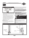
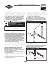
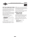
• A manometer port should be provided.
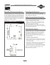
The manometer port permits temporary installation of a
manometer (Figure 5), to ensure that the engine receives
the correct fuel pressure to operate efficiently throughout
its operating range.
NOTE: A digital manometer, P/N 19495, is available at your
local Briggs & Stratton service center.
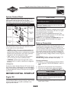
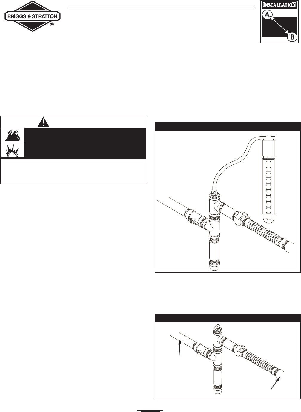
When the initial test runs are completed, the manometer is
removed and the port is plugged.A typical final fuel
connection assembly is shown in Figure 6.
Figure 6 — Completed Fuel Connections
Figure 5 — Temporary Manometer Installed
From Fuel
Supply Line
To Home Standby
Generator
• Before placing the Home Standby Generator into service, the
fuel system lines must be properly purged and leak tested.
• NO leakage is permitted.
Propane and Natural Gas is extremely
flammable and explosive.
Fire or explosion can cause severe burns or
death.
WARNING