


12
Briggs & Stratton Power Products Home Generator
Installation Manual
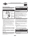
System Control Panel
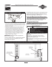
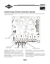
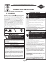
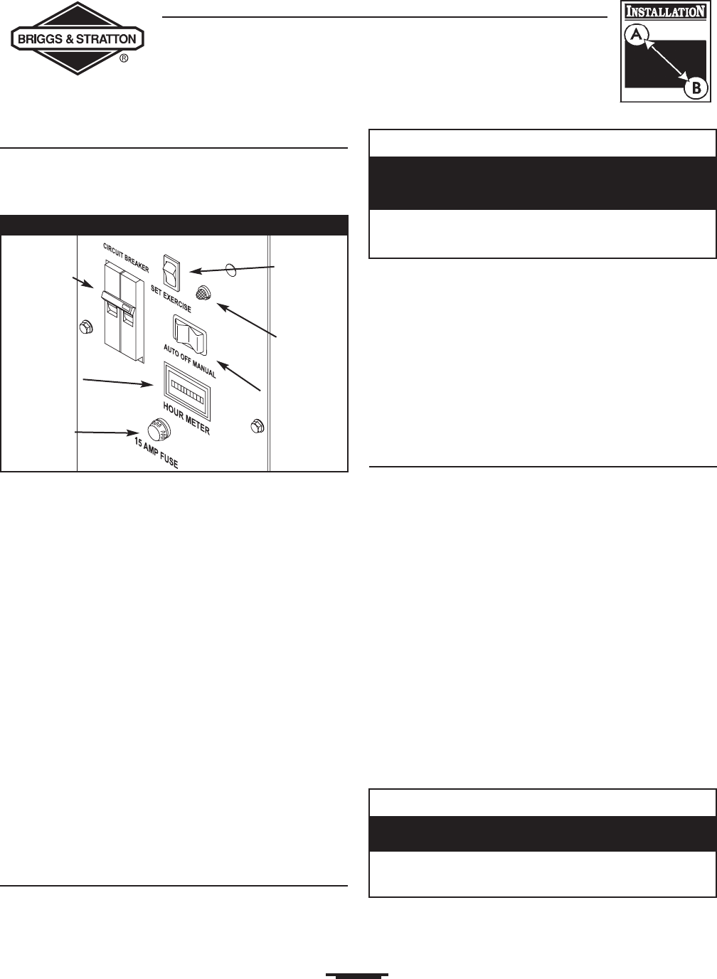
Figure 11 depicts the Home Standby Generator control
panel, located inside the generator housing. Brief
descriptions of the controls used during installation. More
information may be found in the operator’s Manual.
AUTO/OFF/MANUAL Switch
This three-position switch is the most important control
on the system and is used as follows:
•“AUTO” position is the normal operating position. If a
utility power outage is sensed, the system will start the
generator.When utility power is restored, lets the engine
stabilize internal temperatures, shuts off the generator,
and waits for the next utility power outage.
•“OFF” position turns off running generator, prevents
unit from starting and resets any detected faults.
•“MANUAL” position starts the engine after a short
amount of time. It is used for maintenance or diagnostic
functions.
15 Amp Fuse
Protects the Home Standby Generator DC control circuits.
If the fuse has ‘blown’ (melted open) or was removed, the
engine cannot crank or start. Replace the fuse using ONLY
an identical BUS AGC 15A fuse. One spare fuse is supplied
with the unit.
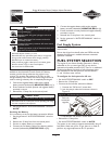
BEFORE INITIAL START-UP
Engine Oil
This engine is shipped from the factory filled with the
recommended oil. Before starting the engine, check oil level
and ensure that engine is serviced as described in the
engine operator’s manual.
Oil Considerations
Your Home Standby Generator is equipped with an engine
that has been pre-run at the factory and does not require
the traditional “break-in” procedure.
The system is filled with synthetic oil (API SJ/CF 5W-
30W).This allows for system operation in the widest range
of temperature and climate conditions.
NOTE: The use of synthetic oil DOES NOT alter the
required oil change intervals described in the engine
operator’s manual.
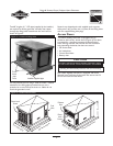
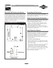
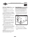
Battery Connection
The Home Standby Generator is supplied with a 12Volt
DC,AGM type, 33 Amp-Hour, valve regulated battery. It is a
sealed, lead-acid rechargeable battery. It is installed in the
unit and the battery cables are connected at the factory.The
unit’s 15 Amp fuse, which isolates the battery and prevents
the unit from starting, has been removed for shipping.The
battery will lose some charge charge prior to installation of
the generator. If battery voltage is below 12Volts, charge the
battery.
IMPORTANT: If battery voltage is below 5 Volts, it may
not take a charge and you will need a new battery.
Charging the Battery
If it is necessary to charge the battery, proceed as follows:
1. Set the generator's “AUTO/OFF/MANUAL” switch to
OFF.
2. Remove the 15 Amp fuse from the control panel.
3. Disconnect the negative battery cable to the negative
battery terminal (indicated by NEGATIVE, NEG, or (-).
4. Charge battery with battery charger at 2 Amps until
battery holds 12 Volts.
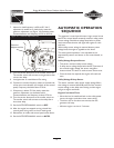
Hour Meter
Circuit
Breaker
Set Exercise
Switch
AUTO/OFF/
MANUAL
Switch
Diagnostic
LED
15 Amp
Fuse
Figure 11 — Home Standby Generator Control Panel
CAUTION
• Refer to engine manual for oil fill information.
• Damage to equipment resulting from failure to follow this
instruction will void warranty.
Any attempt to crank or start the engine before it has
been properly serviced with the recommended oil will
result in equipment failure.
CAUTION
• DO NOT attempt to jump start the battery.
• Damage to equipment resulting from failure to follow this
instruction will void warranty.
Failure to disconnect negative battery cable will result
in equipment failure.