


11
Briggs & Stratton Power Products Home Generator
Installation Manual
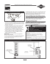
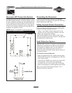
Generator AC Connection System
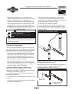
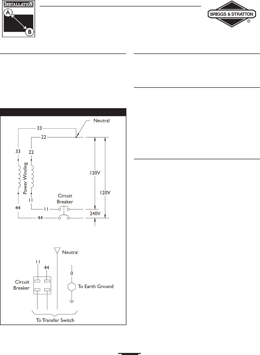
A single-phase, three-wire AC connection system is used in
the Home Standby Generator.The stator assembly consists
of a pair of stationary windings with two leads brought out
of each winding.The junction of leads 22 and 33 forms the
neutral lead, as shown schematically and as wiring diagram
in Figure 10.A complete schematic and wiring diagram can
be found in the operator’s manual.
NOTE: Neutral is not bonded to ground at generator.
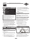
Grounding the Generator
Ground the Home Standby Generator per applicable
codes, standards, and regulations.The generator GND lug is
located inside the air intake door.
Utility Control Circuit Connection
Control circuit interconnections consist of "Utility" leads.
These two leads must be routed in conduit. Control lead
functions are briefly described as follows:
• "Utility 1" and "Utility 2" deliver utility power to the
generator’s circuit board, charge the battery and when
utility is lost the generator will start.
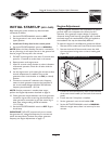
Using installer-supplied minimum 300V, 14 AWG copper
wire, connect each control circuit terminal in the generator
to the Automatic Transfer Switch.
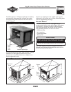
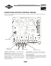
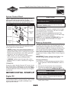
Fault Detection System
The light on the control panel is referred to as the
Diagnostic LED. It will turn on and off in a series of blinks if
certain faults are detected in the HSG.An extra LED and
mounting plate is supplied so that it can be installed at a
convenient indoor location.The owner will use it to
observe the status of the HSG. Consult with the owner for
a convienant location.
To install the remote LED panel:
• Apply the supplied decal to the supplied mounting plate.
• Push the LED through the mounting plate from the front
until it snaps in place.
• Using minimum 18 AWG wire, connect the remote LED
to the generator control board using supplied pin
connectors. Use wire nuts to attach wire to LED leads.
• Attach mounting plate to installer-supplied electrical box.
Refer to the section “Fault Detection System” in the
Operator’s Manual for operation.
Figure 10 — System AC Connections