


OriveBelts{Upperand Lower)
NOTE: The engine pulley must be removed from the
engine's crankshaft in order to change the tractor's
drive belts. Doing so requires an air/impact wrench.
o
o
It is recommended that both belts be changed at the
same time.
Place the deck engagement/lift lever in the
engaged (all the way forward) position.
Unthread the shift knob and remove the two flange
screws which secure the shift cover panel in place.
Refer to Figure 15. Remove the shift cover panel.
NOTE: There is a small yellow wire connected to a
spring switch on the underside of the shift cover panel.
Be careful not to damage it when removing the panel
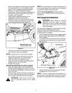
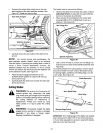
, Using a spring puller (MTD Part No. 732-0571)or
other suitable tool, disconnect the spring which is
attached to a small hook found on the left, rear
portion of the transmission. Refer to Figure 24.
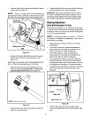
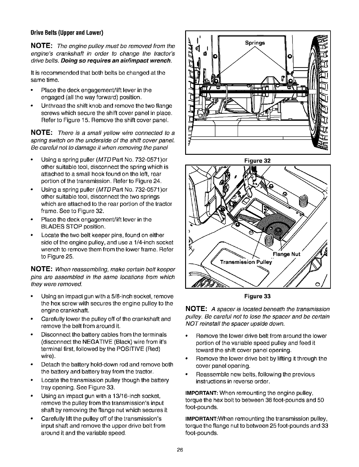
, Using a spring puller (MTD Part No. 732-0571)or
other suitable toot, disconnect the two springs
which are attached to the rear portion of the tractor
frame. See to Figure 32.
, Place the deck engagement/lift lever in the
BLADES STOP position.
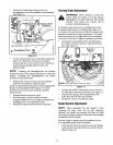
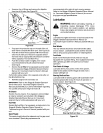
, Locate the two belt keeper pins, found on either
side of the engine pulley, and use a 1/4-inch socket
wrench to remove them from the lower frame. Refer
to Figure 25.
NOTE: When reassembling, make certain belt keeper
pins are assembled in the same locations from which
they were removed.
° Using an impact gun with a 5/8-inch socket, remove
the hex screw with secures the engine pulley to the
engine crankshaft.
° Carefutlylower the pulley off ofthe crankshaft and
remove the belt from around it.
° Disconnect the battery cables from the terminals
(disconnect the NEGATIVE (Black) wire from it's
terminal first, followed by the POSITIVE (Red)
wire).
° Detach the battery hold-down rod and remove both
the battery and battery tray from the tractor.
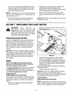
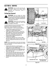
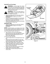
° Locate the transmission pulley though the battery
tray opening. See Figure 33.
° Using an impact gun with a 13/16-inch socket,
remove the pultey from the transmission's input
shaft by removing the flange nut which secures it
° Carefully lift the pulley off of the transmission's
input shaft and remove the upper drive belt from
around it and the variable speed.
°
Figure 32
Transmission
Figure 33
NOTE: A spacer is located beneath the transmission
pulley. Be careful not to lose the spacer and be certain
NOT reinstall the spacer upside down.
, Remove the lower drive belt from around the lower
portion of the variable speed pulley and feed it
toward the shift cover panel opening.
, Remove the lower drive belt by lifting it through the
cover panel opening.
, Reassemble new belts, following the previous
instructions in reverse order.
IMPORTANT: When remounting the engine pulley,
torque the hex bolt to between 38 foot-pounds and 50
foot-pounds.
IMPORTANT:When remounting the transmission pulley,
torque the flange nut to between 25 foot-pounds and 33
foot-pounds.
26