


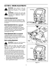
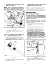
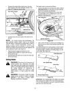
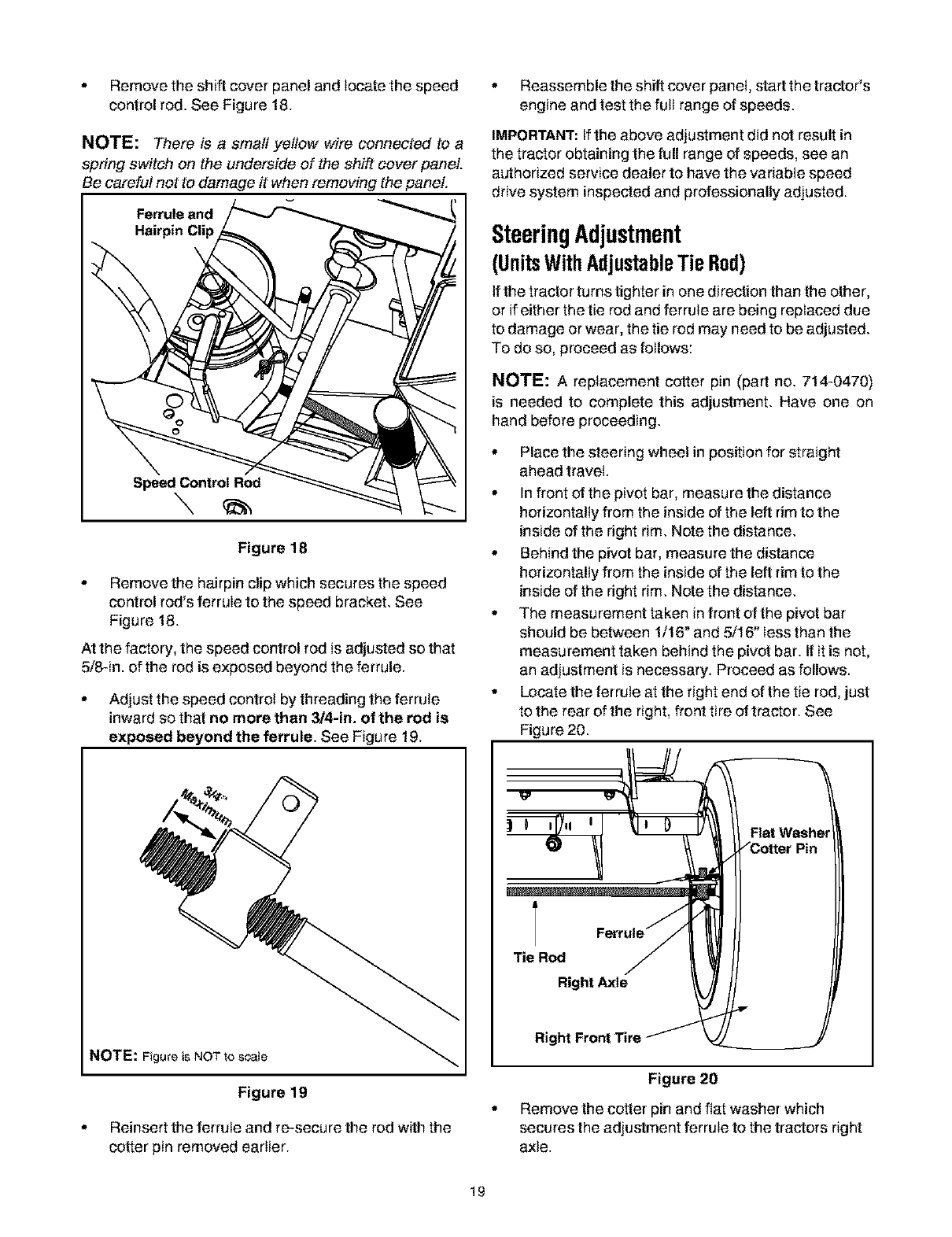
° Removetheshiftcoverpanelandlocatethespeed
controlrod.SeeFigure18.
NOTE: There is a small yellow wire connected to a
spring switch on the underside of the shift cover panel.
Be careful not to damage it when removing the panel.
Ferrule and
Hairpin Clip
Speed Control Rod
Figure 18
° Remove the hairpin clip which secures the speed
control rod's ferrule to the speed bracket. See
Figure 18.
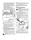
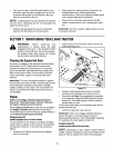
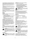
At the factory, the speed control rod is adjusted so that
5/8-in. of the rod is exposed beyond the ferrule.
° Adjust the speed control by threading the ferrule
inward so that no more than 3t4-in. of the rod is
exposed beyond the ferrule. See Figure 19.
NOTE: Fgure is NOT to scale
Figure 19
, Reinsert the ferrute and re-secure the rod with the
cotter pin removed earlier.
° Reassemble the shirt cover panel, start the tractor's
engine and test the futt range of speeds.
IMPORTANT: If the above adjustment did not result in
the tractor obtainingthe full range of speeds, see an
authorized service dealer to have the variable speed
drive system inspected and professionally adjusted.
SteeringAdjustment
(UnitsWithAdjustableTie Rod)
If the tractor turns tighter in one direction than the other,
or ifeither the tie rod and ferrule are being replaced due
to damage orwear, the tie rod may need to be adjusted.
To do so, proceed as follows:
NOTE: A replacement cotter pin (part no. 714-0470)
is needed to complete this adjustment. Have one on
hand before proceeding.
, Place the steering wheel in position for straight
ahead travel.
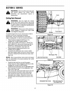
, In front of the pivot bar, measure the distance
horizontally from the inside of the left rim to the
inside of the right rim. Note the distance.
, Behind the pivot bar, measure the distance
horizontally from the inside of the left rim to the
inside of the right rim. Note the distance.
, The measurement taken in front of the pivot bar
should be between 1/16° and 5/16" less than the
measurement taken behind the pivot bar. If it is not,
an adjustment is necessary. Proceed as follows.
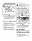
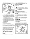
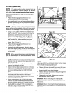
, Locate the ferrule at the right end of the tie rod, just
to the rear of the right, front tire of tractor. See
Figure 20.
Flat Washe
Tie Rod
Right Axle
Right Front Tire
Figure 20
Remove the cotter pin and fiat washer which
secures the adjustment ferrule to the tractors right
axle.
19