


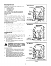
° Measure the distance from the front of the blade tip
to the ground and the rear of the blade tip to the
ground. The first measurement taken should be
between 1/4" and 3/8" less than the second
measu rement. Determine the approximate distance
necessary for proper adjustment and proceed, if
necessary, to the next step.
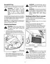
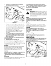
° Place the deck engagement/lift lever in the
engaged (all the way forward) position.
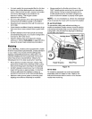
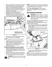
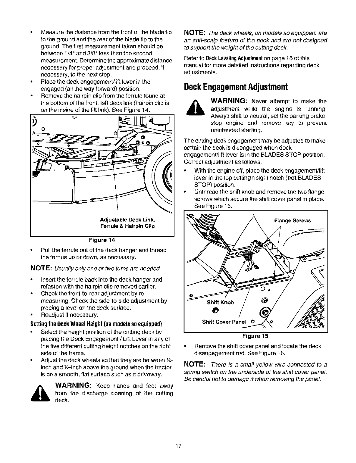
° Remove the hairpin clip from the ferrule found at
the bottom of the front, left deck link (hairpin clip is
on the inside of the lift link). See Figure 14.
O
Adjustable Deck Link,
Ferrule & Hairpin Clip
Figure 14
, Pull the ferrule out of the deck hanger and thread
the ferrule up or down, as necessary.
NOTE: Usually only one ortwo turns are needed.
. Insert the ferrule back into the deck hanger and
refasten with the hairpin clip removed earlier.
° Checkthe front-to-rear adjustment by re-
measuring. Check the side-to-side adjustment by
placing a level on the deck surface.
° Readjust if necessary.
Settingthe OeckWheel Height(on models soequipped)
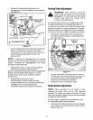
, Select the height position of the cutting deck by
placing the Deck Engagement / Lift Lever in any of
the five different cutting height notches on the right
side of the frame.
° Adjust the deck wheels so that they are between _,_.-
inch and _!_-inchabove the ground when the tractor
is on a smooth, flat surface such as a driveway.
,_ WARNING: Keep hands and feet away
from the discharge opening of the cutting
deck.
NOTE: The deck wheels, on models so equipped, are
an anti-scalp feature of the deck and are not designed
to support the weight of the cutting deck.
Refer to DeckLevelingAdjustmenton page 16 of this
manual for more detailed instructions regarding deck
adjustments.
DeckEngagementAdjustment
WARNING: Never attempt to make the
adjustment while the engine is running.
Always shift to neutral, set the parking brake,
stop engine and remove key to prevent
unintended s_arting.
The cutting deck engagement may be adjusted to make
certain the deck is disengaged when deck
engagement/lift lever is in the BLADES STOP position.
Correct adjustment as follows.
. With the engine off, place the deck engagement/lift
lever in the top cutting height notch (not BLADES
STOP) position.
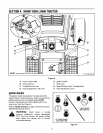
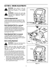
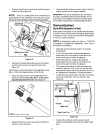
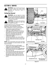
. Unthread the shift knob and remove the two flange
screws which secure the shift cover panel in place.
See Figure 15.
Flange Screws
Shift Knob
Shift Cover Panel
Figure 15
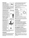
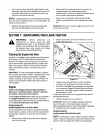
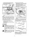
, Remove the shift cover panel and locate the deck
disengagement rod. See Figure 16.
NOTE: There is a small yellow wire connected to a
spring switch on the underside of the shift cover panel.
Be careful not to damage it when removing the panel.
17