


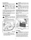

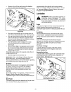
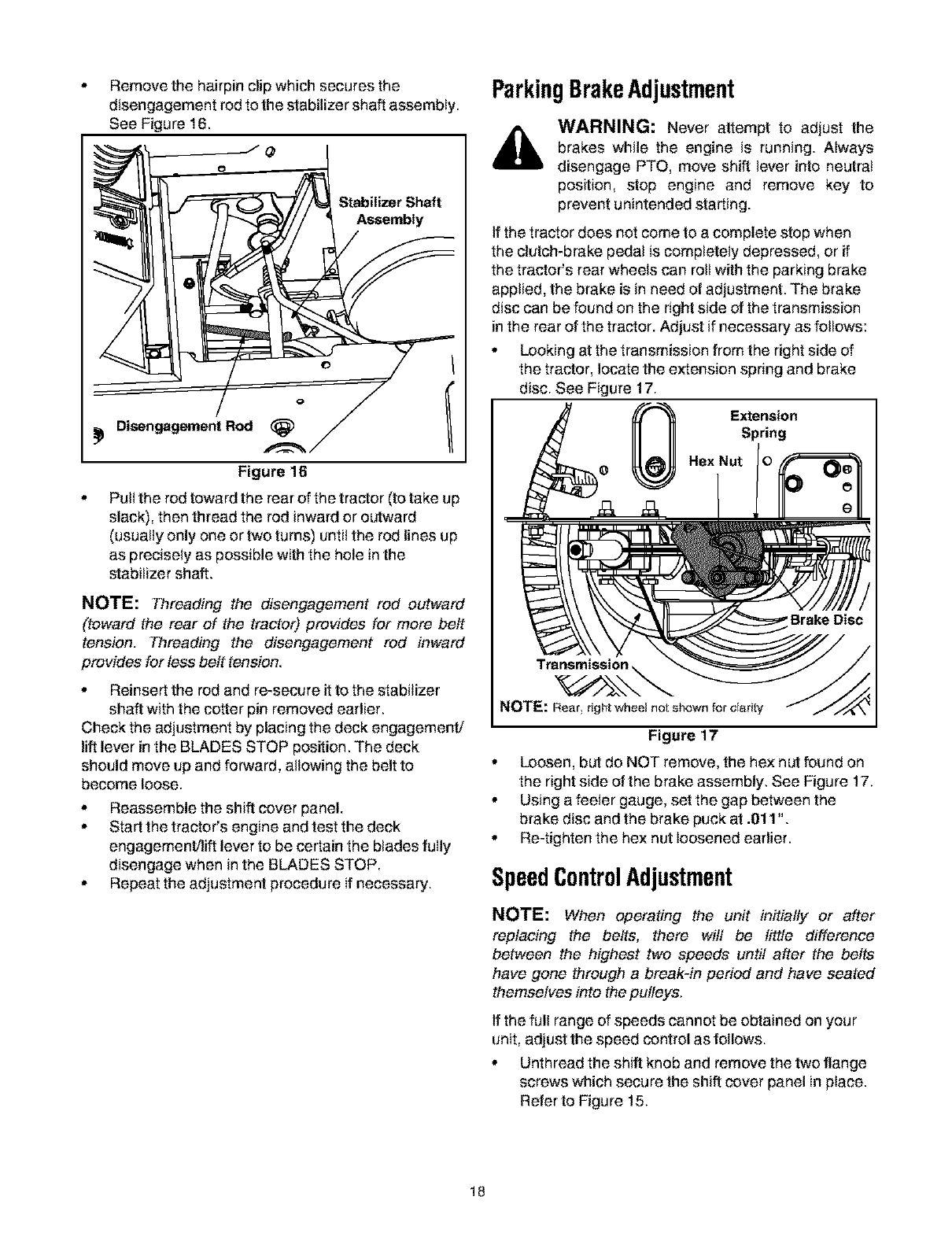
Remove the hairpin clip which secures the
o
disengagement rod to the stabilizer shaft assembly.
See Figure 16.
ParkingBrakeAdjustment
,i_ WARNING: Never attempt to adjust the
_ ._ brakes while the engine is running. Always
• o disengage PTO, move shift lever into neutral
position, stop engine and remove key to
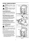
Stabilizer Shaft prevent unintended starting.
"_JIl_l I_1 / /""_///// _ Assembly _ .
Looking at the transmission from the right side of
the tractor, locate the extension spring and brake
Disengagement Rod ExtensionSpring
Figure 16 o Hex Nut
o Pult the rod toward the rear of the tractor (to take up
slack), then thread the rod inward or outward
(usually only one or two turns) untit the rod lines up
as precisely as possible with the hole in the
stabilizer shall.
NOTE: Threading the disengagement rod outward
(toward the rear of the tractor) provides for more belt
tension. Threading the disengagement rod inward
provides for less belt tension.
o Reinsert the rod and re-secure it to the stabilizer
shaft with the cotter pin removed earlier.
Check the adjustment by placing the deck engagement/
lift lever in the BLADES STOP position. The deck
should move up and forward, allowing the belt to
become loose.
o Reassemble the shift cover panel.
o Start the tractor's engine and test the deck
engagement/lift lever to be certain the blades fuIly
disengage when in the BLADES STOP.
o Repeat the adjustment procedure if necessary.
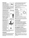
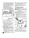
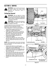
Transmission
NOTE: Rear, right wheel not shown for elarib]
Figure 17
o Loosen, but do NOT remove, the he:<nut found on
the right side of the brake assembly. See Figure 17.
o Using a feeler gauge, set the gap between the
brake disc and the brake puck at .011 ".
o Re-tighten the hex nut loosened earlier.
SpeedControlAdjustment
NOTE: When operating the unit initially or after
replacing the belts, there wilt be little difference
between the highest two speeds until after the belts
have gone through a break-in period and have seated
themselves into the pulleys.
If the full range of speeds cannot be obtained on your
unit, adjust the speed control as follows.
o Unthread the shift knob and remove the two flange
screws which secure the shift cover panel in place.
Refer to Figure 15.
18