


Features and Controls
3
Section
7
OPERATING SYMBOLS
Various symbols (shown here, with
word descriptions) are used on the
unit.
STOP
FEATURES AND CONTROLS
This Section describes the location and
function of the features and controls on
your machine. Refer to the following
Operation Section for detailed operating
instructions.
Do not start the engine until you read and
understand all safety, controls and oper-
ating instructions in this Manual, the sep-
arate Engine Owner’s Manual, and on the
decals on the machine.
IMPORTANT: Refer to the separate
Engine Owner’s Manual for detailed infor-
mation about the controls on the engine.
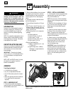
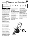
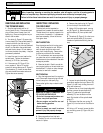
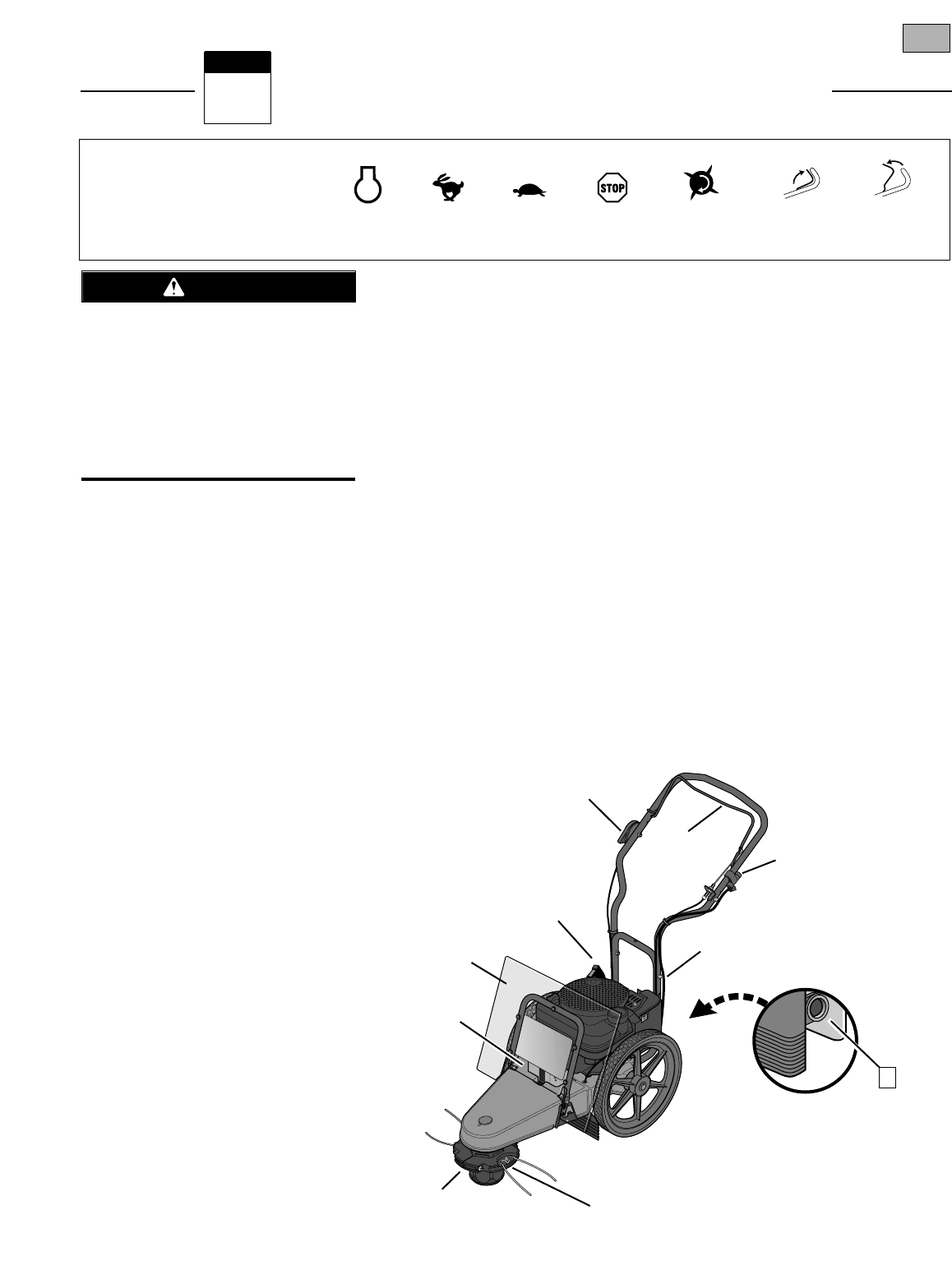
TRIMMER HEAD CONTROL BAIL
Pull the control bail (A, Figure 3-1) up
against the handlebar (engage bail) to
start rotation of the trimmer head. Let go
of the control bail (disengage bail) to
stop the trimmer head.
CUTTING HEIGHT SETTINGS
The trimmer head (B, Figure 3-1) is
adjustable to an infinite number of height
settings from 1-1/2" -to- 4-1/2".
TRIMMER LINE HOLDERS
The trimmer lines are secured to line
holders (C, Figure 3-1). Replacing the
trimmer lines is a simple procedure (see
Changing Trimming Lines in Section 5).
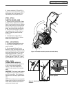
HANDLEBAR HEIGHT ADJUSTMENT
The handlebar (D, Figure 3-1) has two
height settings (see Adjust Handlebar
Height in the Operation Section).
PLASTIC DEBRIS SHIELD
The plastic debris shield (E, Figure 3-1)
protects the engine from all manner of
debris. The shield tilts forward for
access to the engine.
ENGINE THROTTLE CONTROL LEVER
Use this lever (F, Figure 3-1) to regulate
engine speed and to stop the engine. The
throttle settings are shown on the decal
next to the lever.
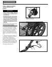
ENGINE RECOIL STARTER
The recoil starter (G, Figure 3-1) is
located at the rear of the engine and is
used to pull start the engine.
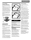
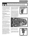
FUEL PRIMER BUTTON
The fuel primer button (I, Figure 3-2)
allows a cold engine to be primed for
faster, easier starting.
KEYSWITCH
(ELECTRIC START MODEL)
On electric start models, the keyswitch
(J, Figure 3-1) is used to start the engine.
The keyswitch does not have an engine
stop position. Use the Engine Throttle
Control Lever (F) to stop the engine.
IMPORTANT: Remove key from
keyswitch when leaving unit unattended
to help prevent unauthorized or uninten-
tional starting.
BATTERY (ELECTRIC START MODEL)
On electric start models, the battery (K,
Figure 3-1) will crank the engine starter
motor when the keyswitch is turned to
the start position. Do not crank engine
longer than five (5) seconds per each
starting attempt.
ENGINE
STOP
TRIMMER
HEAD
ENGAGE
BAIL
DISENGAGE
BAIL
SLOW
FAST
STOP
Figure 3-1: Features and controls (electric start model shown).
J
C
B
G
K
F
A
E
I
D
Before operating your machine, care-
fully read and understand all safety,
controls and operating instructions in
this Manual, the separate Engine
Owner’s Manual, and on the decals on
the machine.
Failure to follow these instructions can
result in serious personal injury.
WARNING