


Section 5: Maintenance 13
Before inspecting, cleaning or servicing the machine, shut off engine, wait for all moving parts to
come to a complete stop, disconnect spark plug wire and move wire away from spark plug.
Failure to follow these instructions can result in serious personal injury or property damage.
WARNING
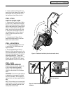
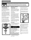
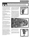
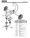
11. Using a 9/16" wrench and a 7/32" hex
(Allen) wrench, loosen the mounting nut
(G, Figure 5-6) and screw on the idler
pulley (I) a few turns, or until belt is free
to slip out between pulley and belt guide
(J). Remove belt.
12. Loosen rear belt guide screw (K,
Figure 5-6) enough to allow belt to be
removed from engine pulley (L). Remove
belt from unit.
BELT REPLACEMENT
1. Install belt on engine pulley (L, Figure
5-6) and retighten rear belt guide screw
(K) securely.
2. Route belt between idler pulley (I,
Figure 5-6) and belt guide (J), to inside of
brake arm (M), and next to die-cast belt
guides (N).
3. Securely tighten the mounting nut (G,
Figure 5-6) and screw in the idler pulley
(I).
4. Securely tighten the idler arm
mounting screw (S, Figure 5-6). After
tightening, check that idler arm is free to
rotate. If not, remove idler arm and check
for debris that may be interfering with
freedom of movement.
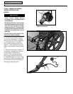
5. Look at the spindle head mounting
hole (O, Figure 5-6) and note the grooves
that are cut into the inner sides of the
hole. These grooves were formed by the
splines on the spindle shaft (E, Figure
5-5).
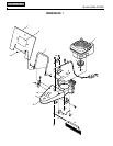
6. Install the belt on the spindle head
pulley (P, Figure 5-5) and insert the
spindle shaft (E) (with attached spindle
head assembly) into the spindle head
mounting hole (O, Figure 5-6). Rotate the
spindle head assembly to align the
splines on the spindle shaft with the
grooves in the mounting hole. Check
that the belt is still in the pulley groove
and is to the inside of the die-cast belt
guides (N, Figure 5-6).
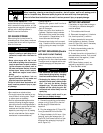
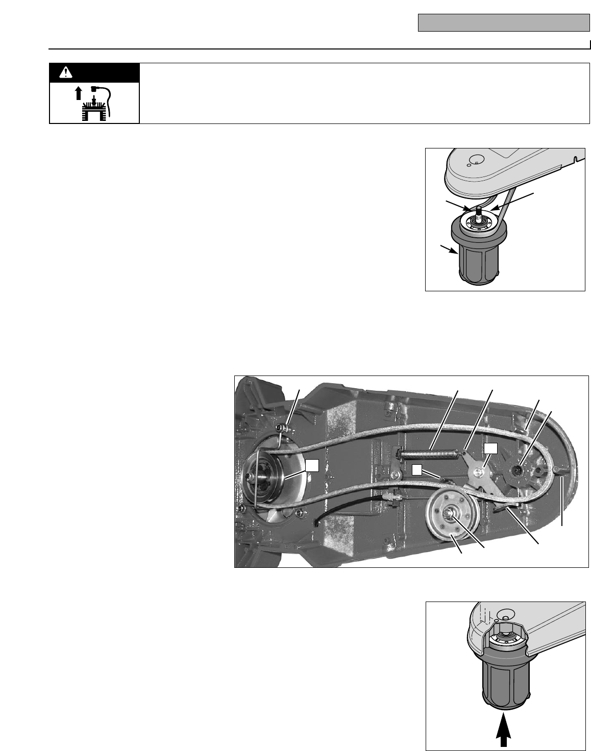
7. Using a firm push on the spindle head
assembly (Figure 5-6A), seat the spindle
head assembly into the hole. Check that
the threaded end of the spindle shaft is
protruding through the bottom of the
hole.
8. Reinstall the flat washer (D, Figure 5-
4), Belleville washer (C) and nut (B) on
the spindle shaft. Note that the dished-in
side of the Belleville washer must face
the flat washer. Tighten the nut securely
(torque to 50 ft./lbs.), while checking fre-
quently to ensure that the spindle head
rotates freely. If the spindle head binds,
it could be due to the belt being pinched
between the spindle head and the belt
guides. If so, remove the spindle head
assembly and repeat steps 5-7.
9. Replace plastic plug (A, Figure 5-4).
10. Reattach the idler arm spring (R,
Figure 5-6) in the hole in the idler arm
(T).
11. A new belt may need to be adjusted
by following the Adjusting Trimmer Head
Engagement instructions in this Section.
Figure 5-5
Figure 5-6
E
F
P
R
T
K
N
N
O
M
G
I
S
J
L
Figure 5-6A