


BK Precision 4070A User Manual Rev.2.2
49
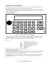
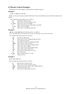
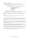
7.4 Arbitrary Waveform Mode
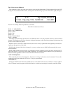
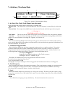
Figure 7.4-1: Arbitrary Waveform Mode display
1. Int Clock / Ext Clock / Lock Master Lock slave mode
In this field select the clocking mode for the arbitrary waveform system:
Internal Clock - The sample clock is generated internally. The clock frequency is entered directly via the front
panel.
External Clock - The sample clock (40 MHz max) is taken from the External Arb Clock input on the back panel.
*** Warning ***
TTL/CMOS levels (0V to +5V) only.
Lock Master - The unit provides the master timing signals for locking multiple 4070A Arb generators together.
Lock Slave - The unit receives all timing signals from a master unit. Used when locking multiple 4070A Arb’s
together. For more information on locking Arb’s together, see the section 7.9.
2. Phase
This field is used during Multiple Unit Locking and only appears when the unit is in Lock Slave mode. It allows
you to specify a phase offset of the arbitrary waveform relative to the waveform being generated by the Master Unit.
For more information, see section 7.9.
3. Continuous/Triggered mode
In this field select whether the waveform is generated continuously or on a single event basis. If you select
Continuous mode, then the waveform is immediately restarted once the last point is reached. If you select a
Triggered mode, then the waveform generation is halted after the last point is reached, and the waveform is not
restarted again until another trigger occurs. The trigger can come from three sources:
1. Pressing the Trigger key
2. Applying a low-to-high transition on the Ext. Trig In connector
3. Sending an ASCII "T" to the RS-232 port
The 4070A will simultaneously accept a trigger from all of the above sources.
To set Continuous-triggering mode, press 1.
To set Triggered mode, press 0.
Pressing any arrow key or rotating the wheel will toggle the run mode between Continuous and Triggered.
4. Clock Frequency
In this field enter the Arbitrary Waveform clock frequency. This is the frequency at which your waveform values
are sent to the Digital to Analog converter (DAC). You may enter from 0 Hz (DC) to 40.0 MHz in 0.01 Hz steps.
If a value of 0 Hz is entered, the arbitrary waveform clock is halted.
5. Level
In this field enter the output level, from 4 mVp-p to 10 Vp-p in 1 mV steps. This level is the peak-to-peak voltage
swing of the waveform across a 50O loaded, into an open circuit, the voltage swing will be twice the specified peak-
to-peak value.
Offset
Enter a DC offset voltage by pressing the Offset key. For more information refer to section 4.4.
Arb Mode
Int
Clock
Phase: 126.35 deg
Cont Clock: 1,000,000.00 Hz 10,000 mV
3
1
4
2
5