


BK Precision 4070A User Manual Rev.2.2
47
7.2 Introduction to the Arbitrary Waveform System
7.2.1 Description of the Arbitrary Waveform Generator
The Arbitrary Mode lets the user design custom waveforms on a PC and download them to the 4070A for
generation including Arbitrary Waveform system is a fully featured Function Generator. Function generator offers a
set of pre-stored waveforms. Signals are generated using the Arbitrary Waveform hardware. User may select from
many stored waveforms, and may also specify a repetition rate to 2 MHz. All functions could be generating on a
continuous or triggered basis. High-going pulse is given on the SYNC Out connector at the start of each waveform.
Also included with the Arbitrary Waveform system is a variable duty cycle Pulse Generator. Pulse Generator
allows the user to generate pulse waveforms with varying amplitude, offset, frequency and duty cycle
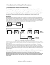
Introduction
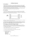
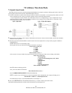
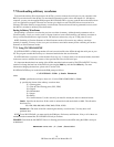
Output signal form is generated by sending values to a Digital to Analog converter (DAC) from a ram memory.
High-speed counter generates sequential addresses which indexes successive ram values for the DAC, clock for the
counter is derived from the same DDS system used to generate the DC-21.5 MHz output of the 4070A. Because the
Arbitrary waveform system uses the fully synthesized DDS system for its clock, the arbitrary waveform generator
has a highly accurate and stable clock source adjustable from DC to 40 MHz in .01 Hz steps.
DDS
Clock
Generator
Freq.
Doubler
DC
-
20 MHz
Counter
32K x 16
RAM
12 Bit
DAC
Low Pass
Filter
Gain
Control
TTL/CMOS
Buffer
SYNC Out
(Front Panel)
SIG Out
(Front Panel)
DC
-
40 MHz clock
Counts 0,1,...N,0,1,...
Extra Data bit
15
13
9th Order Bessel
Fc = 10 MHz
Addr
Data
Figure 7.2.1-1: Arbitrary Waveform Generator block diagram
Logic level output is provided on the SYNC Out connector. This output signal could be used to assert a digital
pulse on any data point, with is useful to generate synchronous pulses with the analog data or to generate arbitrary
digital waveforms.
The 4070A receives arbitrary waveform data through the serial port on the rear of the 4070A. An incoming
waveform is stored in successive ram locations beginning at address 0. After the last data point is received, the
system processor adds a special “end of data” bit to the last data point, instructing the counter hardware to reset to
the waveform start address after the last data point is sent to the DAC. Waveforms may be conveniently saved to
nonvolatile memory.
Those waveform values could be sent to the 4070A in a variety of formats. ASCII formats include floating point,
time & value floating point, decimal, hexadecimal, and integer. Binary format is also supported.
Waveforms may be generated in Continuous or Triggered modes. In continuous mode, the waveform is
immediately restarted after the last point in the waveform is generated. In Triggered mode, the waveform halts after
the last data point has been generated. The system then awaits another Trigger condition before generating the
waveform again.