


BK Precision 4070A User Manual Rev.2.2
7
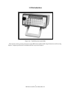
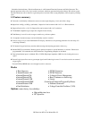
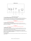
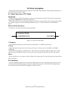
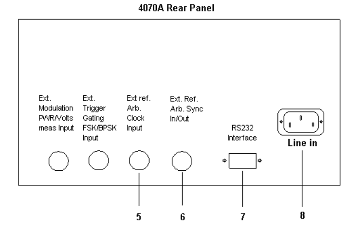
Figure 2.0-5: Rear panel connectors
5. External Reference Input / Ext Arb. Clock connector
This connector accepts an external sample clock for the Arbitrary Waveform Generator when the unit is in
External Clock or Lock Slave modes. The signal level on this input must be between 0V and +5V and is intended to
be driven by TTL/CMOS logic. (For more information on Arb Locking, refer to the chapter “Multiple Unit
Locking.”) This connector is also reserved for the addition of an external time base reference option.
*** Caution ***
Logic signals outside the 0V to +5V range on this input may damage the 4070A.
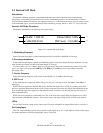
6. External Arb Sync In / Out connector
This connector accepts an external synchronizing signal when the unit is in Lock Slave mode. (For more
information on Arb Locking, refer to the chapter “Multiple Unit Locking.”) The signal level on this input must be
between 0V and +5V, TTL/CMOS.
*** Caution ***
Logic signals outside the 0V to +5V range on this input may damage the 4070A.
7. RS232 Interface connector
This port is used for: remote operation of the 4070A, software upgrades to internal Flash memory. To use the
remote control feature, attach the serial port on a computer or terminal to the RS-232 Interface connector, on the
back panel of the 4070A, on PC to the serial port connector.
The wiring is different for each type of connector. For cabling diagrams, see chapter 6 "Remote Operation."
Baud rate is factory-set to 9600 but may be changed via the front panel or RS232 port. The other serial port
parameters are 1 start bit, 8 data bits, 1 stop bit, and no parity. An ASCII "hello" screen is printed to the terminal on
power-up. For further information, refer to chapter 6.
8. Line in connector
A standard IEC power cord inserts directly into the back of the 4070A. The input is auto-ranging and may be 100-
240VAC, 47-63 Hz.