


Part No. 520166 Form No. F112003A
11
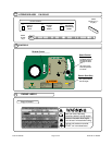
ASSEMBLY
..
..
Page 4 of 20
PUT OIL IN ENGINE BEFORE STARTING.
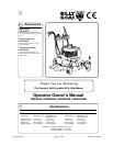
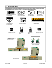
Read all safety and operating instructions
before assembling or starting this unit.
Your Billy Goat Mower is shipped from the factory
in one crate, completely assembled except for the
handles and console assembly.
DISCONNECT SPARK PLUG WIRE
BEFORE ASSEMBLING UNIT.
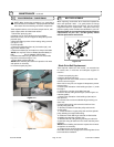
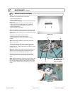
8. Insert one of the handle mounting bolts (Item 102) with Hex. lock washer
(Item 6) through the rear handle mounting hole of the right side handle,
and screw it into the rear handle mounting hole on the right side of engine
base chassis (Item 61). Repeat this
procedure for the left side using the
left handle.
9.On each side of the mower, insert
one of the handle mounting bolts
(Item 102) with Hex. lock washer
(Item 6) through the hole in one
end of the handle brace (Item 32),
the front handle mounting hole of
the handle and screw into the front
handle mounting hole in the engine
base chassis (Figure 11-5).
10.Using one of the bolts and fl at
washers removed previously (step
8), insert the bolt with washer, from
the outside, through the bottom hole
on the console, through the handle,
through the top hole of the handle
brace, through one of the fl at wash-
ers removed in step 8 and secure
with lock nut (Item 151). Repeat this
procedure for the bottom hole on
the other side of the console. Make
sure control cables are free and not
damaged while tightening console
mounting bolts (Figure 6).
11.On the left hand side, using
one of the bolts and fl at washers
removed previously (step 6), insert
the bolt with washer, from the
outside, through the top hole on
the console, through the handle,
through the control cable retainer,
through one of the fl at washers
removed in step 8 and secure with
lock nut (Item 151). Repeat for right-
hand side except there is no control
cable retainer for this side. Make
sure the control cables are not
damaged while tightening console
mounting bolts (see fi gure 11-6).
12.Finish mounting handle to
engine base bolts then fi nish tight-
ening the remaining bolts.
13.Position control cables and use
2 cable ties on each handle to
secure the cables in position. The
top cable tie should be 1” below the
console and the lower tie should be
12” below the console (see fi gure
11-7)
14.Check the position of the shift rod
guide (Item 69), and if necessary,
snap it in place in the shift bracket
(Item 78) as shown in Figure 11-8.
15.Put shift lever in NEUTRAL,
depress the brake lever (release
the brake) and carefully pull the
machine back off the pallet.
16.Fill with oil and gas to the proper
level and the unit is ready to mow.
(a battery will also have to be
installed on electric models.)
17.Read the operator’s manual.
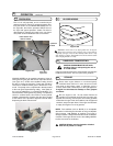
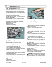
1.Cut and remove the nylon retaining straps (see fi gure 11-1).
2.Pry up and remove the shipping crate’s top panel.
3.Remove the shipping crate’s end panel at rear of mower
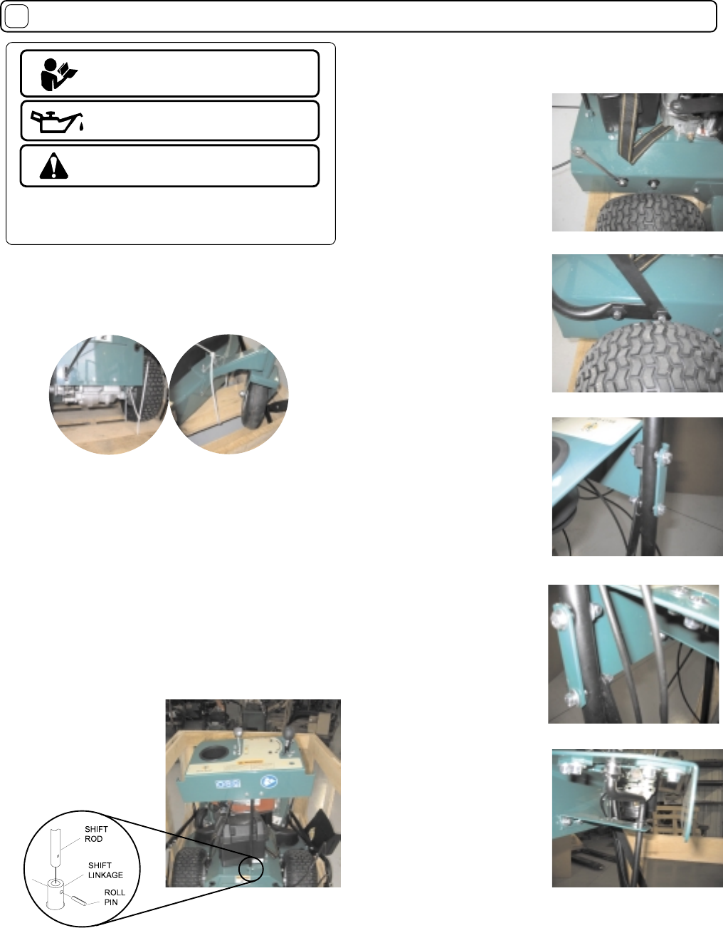
4.With the console positioned as shown in Figure 11-3, insert the shift
linkage rod (Item 31) into the shift linkage connector (Item 54).
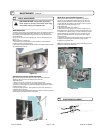
5. To assemble the shift rod (item 31) to the shift linkage (item 54),
use the roll pin in the parts/literature bag. If you’ll notice on the shift
linkage, the hole is larger on one side than the other.
It will be easier to start the roll pin from the larger side, forcing it
through the shift rod and the hole on the other side of the shift linkage,
using a hammer or large adjustable pliers.
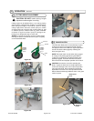
6.Remove and retain for reuse console mounting bolts, washers and
nuts (Items 135, 150 & 151) from left and right handles.
7.Remove and retain for reuse handle mounting bolts and hex lock
washers (Items 102 & 6) located just above the rear wheels on each
side of mower (see fi gure 11-4).
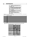
NOTE: Fasteners should only
be tightened snug tight until
handle and console assembly
is complete.
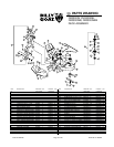
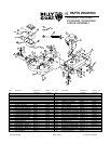
NOTE: All item numbers called out in the assembly,
operation, and maintenance sections of this manual can
be found on Parts List (pages 15-18).
Figure 11-1
Figure 11-3
Figure 11-4
Figure 11-5
Figure 11-6
Figure 11-7
Figure 11-8