


Part No. 520166 Form No. F112003A
Page 12 of 20
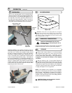
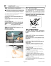
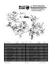
NOTE: When sharpening the blade it is a good idea to
check the balance of the blade. A properly balanced blade
will increase life of the bearings and other components.
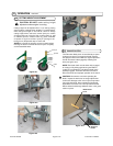
Tools required: ratchet, 3/4” inch socket, torque wrench, ade-
quate support, block to inhibit blade rotation.
1. Disconnect spark plug wire.
2. Support front of unit to allow access to the blades.
Note: Unit is heavy. Be sure support is adequate to prevent
personal injury.
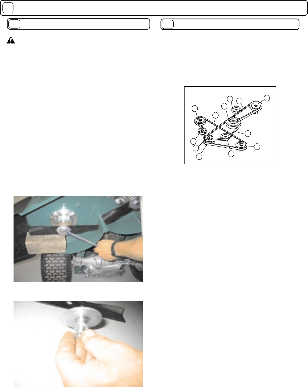
3. Block the blade to prevent it from rotating during removal
(see fi gure 17-4).
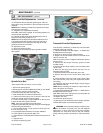
For Each Spindle:
4. Remove the blade bolt (Item 35), lock washer (33), and
large friction washer (103).
5. Remove the blade (18) and replace or sharpen the blade.
NOTE: Use only B.G.I. Part no. 520001(Standard blade) or
B.G.I. Part no. 520002 ( Mulch blade).
6. Reinstall the blade using all fasteners in the exact order
they were removed (see fi gure 17-4).
7. Torque blade screw to 60 ft-lbs.
NOTE: Before installing the fasteners inspect them for wear
and replace as necessary.
8. Reconnect spark plug wire.
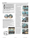
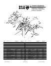
When replacing one belt the other should be inspected for
wear and replaced if worn. It is good practice to change
both belts when either is worn beyond use. Use only original
equipment belts for replacement. Billy Goat uses only
premium quality, kevlar corded and coated belts in your unit.
Substitute belts do not meet the design and performance
requirements for your unit , and will greatly reduce
machine performance and belt life.
BELT REPLACEMENT
17.5
MAINTENANCE continued
17
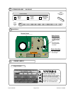
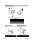
Figure 17-6
Figure 17-4
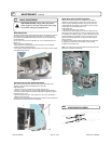
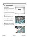
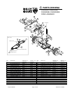
Blade Drive Belt Replacement
Tools required: ratchet, 3/4 inch socket, 10” extension bar
for socket, two ½” wrenches and adequate support for
machine.
1. Disconnect spark plug wire.
2. Remove the deck belt cover.
3. Support front of unit to allow access to underside of the
machine near the engine.
Note: Unit is heavy. Be sure support is adequate to prevent
personal injury.
4. Observe the orientation of the belt fi ngers (Item 71) under
the engine.
5. Remove the 4 engine mount bolts (Item 48)
6. Remove the left and right belt fi ngers (These fi ngers are
interchangeable).
7. Observe the orientation of the belt fi nger (Item 90) on
idler (Item 91).
8. Loosen but do not remove idler/belt fi nger retaining nut
(Item 144).
9. Observe belt routing and remove the belt from front
spindle pulley (Item 46).
10. Remove the belt from the idler pulley and from the
engine pulley.
11. Install new belt on engine pulley, idler and front spindle
pulley following the original belt routing.
12. Position the idler belt fi nger centered on idler bracket
and tighten the retaining nut (Item 144).
13. Reinstall the left and right belt guide fi ngers under the
engine base using all fasteners in the exact order they were
removed.
NOTE: Before installing the fasteners inspect them for wear
and replace as necessary.
14. Torque the four engine bolts to 40 ft-lbs.
Note: With clutch levers engaged, be sure belt guides do not
touch belts after installation.
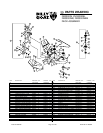
50
105
171
24
37
171
23
85
171
22
19
26
Figure 17-5
BLADE REMOVAL / SHARPENING
17.4