


4-22 Operation MN2408
Operator Control Panel
(Analog Engine Controller Only)
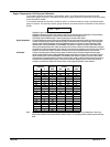
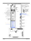
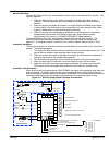
Figure 4-10 Analog Operator Control Panel
–+
OFF
1
2
3
Panel Lights switch (On-Off )
Turns on two lamps to illuminate the operator panel.
Panel Light Fuse
Fuse for panel lights.
Master Control switch (Manual Run-Stop - Auto Start)
Manual Run - Starts the engine manually.
Stop - Stops the engine and generator.
Auto Start - Starts the engine when the Remote start" terminals are
closed.
Display Lamps
High Temperature - Indicates excessive engine coolant temperature.
Low Oil Pressure - Indicates low engine oil pressure.
Overspeed - Indicates engine speed is greater than preset limit.
Overcrank - Failure of the engine to start by the end of the crank period
results in an overcrank" shutdown and alarm indication.
Voltage Adjust
Increase or Decrease the Generator output voltage (displayed on
VOLTAGE meter)
AC Voltage meter
Analog display of generator output voltage in RMS volts.
AMMETER switch (3 position)
Off - No current is measured by the Amperage meter.
1 - Phase 1 current is measured by the Amperage meter.
2 - Phase 2 current is measured by the Amperage meter.
3 - Phase 3 current is measured by the Amperage meter.
Amperage meter
Analog display of generator output current in RMS amps.
Hertz meter
Analog display of generator output frequency in Hertz.
Battery Voltage meter
Displays the voltage of the engine starting battery.
Engine Temperature meter
Displays the temperature of the engine coolant.
Oil Pressure meter
Displays engine oil pressure.
Run Time (Hours) meter
Total elapsed time indicator of generator set operation.
PANEL LIGHTS
ON OFF
MASTER
CONTROL
MANUAL
RUN
AUTO
START
STOP
OVERSPEED
OVERCRANK
HIGH TEMPERATURE
LOW OIL PRESSURE
VOLTAGE AMPERAGE
AMMETER
HERTZ
PANEL LIGHT
FUSE
VOLTAGE
ADJUST
Oil PressureBattery
Volts
Engine
Temp
RUN TIME (HOURS)
Panel LightPanel Light
Operating Procedures The engine–generator controller is designed to start and stop an engine from either a local
(“Manual”) or remote (“Automatic”) mode. When a start command is issued, the controller issues
a run and crank output signal. The controller then monitors engine speed and when crank
disconnect speed is reached, the crank signal is terminated. While the engine accelerates to
normal speed, the controller continuously monitors the engines speed signal. Should the engine
speed exceed the maximum predetermined setpoint, the overspeed shutdown fault circuit will
activate, terminating the run signal.
In addition to overspeed shutdown, the engine controller also monitors many other engine
protection circuits and should they be activated, the engine will be stopped and/or alarm initiated.
The engine will automatically stop for any shutdown condition, or when the remote and/or local
start signal is removed. The engine controller operation includes time delay circuits for normal
operating conditions such as start delays, cool down and cranking periods.