


Page 17 of 45
GASEOUS FUEL INFORMATION
INCORRECT INSTALLATION OF THIS GENERATOR SET COULD RESULT
IN PROPERTY DAMAGE, INJURY, OR DEATH! INSTALLATION OF THIS
GENERATOR SET MUST BE PERFORMED BY A QUALIFIED,
PROFESSIONAL TECHNICIAN OR CONTRACTOR.
THIS INFORMATION IS FOR GENERAL REFERENCE ONLY! IT MUST NOT
BE USED AS THE SINGLE SOURCE OF INFORMATION FOR INSTALLING
THE GENERATOR SET. FOR MORE SPECIFIC/DETAILED INFORMATION
READ THE INSTALLATION MANUAL THAT ACCOMPANIED THE
GENERATOR SET.
Before undertaking installation of gaseous fuel supply piping from a remote fuel source to the
generator set, a check should be made concerning local and state regulations governing the
use, application, and installation of gaseous fuel. These regulations along with the standards set
forth by the NFPA (National Fire Protection Agency) should be followed for safe, dependable,
and proper installation.
The applicable NFPA regulations are covered in the following NFPA Publications:
No. 37 - Combustion Engines No.
54 - Gaseous Appliances and piping
No. 58 - Storage and handling LPG
These publications are available at a nominal price from:
The National Fire Protection Agency P.O. Box 9101 Quincy, MA 02269
GASEOUS FUEL SUPPLY PIPING
GASEOUS FUELS ARE HIGHLY COMBUSTIBLE AND CAN CAUSE
EXPLOSIONS, FIRE, INJURY, OR DEATH! THE FUEL SUPPLY SYSTEM MUST
ONLY BE INSTALLED AND ADJUSTED BY AN EXPERIENCE, PROFESSIONAL
TECHNICIAN USING APPROVED PIPING AND COMPONENTRY.
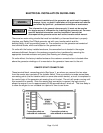
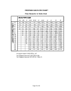
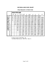
For the purpose of calculating piping size, the fuel consumption of an engine is figured at
approximately 10,000 BTU's needed per horsepower per hour. For example, a 10 horsepower
engine will require 100,000 BTU's of gaseous fuel per hour. Operating on natural gas which
contains 1,000 BTU's per cubic foot, this engine would require 100 cubic feet of natural gas an
hour to operate properly. In addition to fuel consumption, the following factors must be
considered when installing the gaseous fuel supply piping:
1. Pressure loss due to the number of fittings (elbows, reducers, etc.).
2. Specific gravity of the gaseous fuel.
3. Pressure loss due to the length of the fuel supply piping.
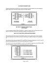
The accompanying gas flow/pipe capacity charts list the capacity of various sizes and pipe run
lengths. The capacity, which is given in cubic feet per hour, is calculated for both propane and