


Page 13 of 45
ELECTRICAL INSTALLATION GUIDELINES
Incorrect installation of the generator set could result in property
damage, injury, or death! Installation of this generator set must be
performed by qualified / professional technicians or contractors.
This information is for general reference only! It must not be used as
the single source of information for installing the generator set. For more
specific/detailed information read the installation manual that
accompanied the generator set as well as the transfer switch manual.
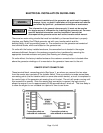
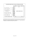
There are two main wiring circuits that must be installed by a licensed electrician to properly
interface your Baldor Pow'R Gard generator set with your transfer switch and the
building/facility it will be providing power to. The connection on the generator set consists of
two terminal blocks, which are located on the generator set.
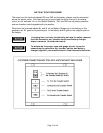
On units with the factory installed enclosure, the connection box is located in the engine
enclosure bulkhead. Access to the customer connection box is achieved by removing the
appropriate louvered enclosure end panel (See Drawing on following page).
On units without the factory installed enclosure the customer connection box is located either
above the generator windings or it is mounted on the generator frame next to the unit.
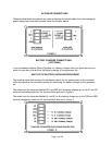
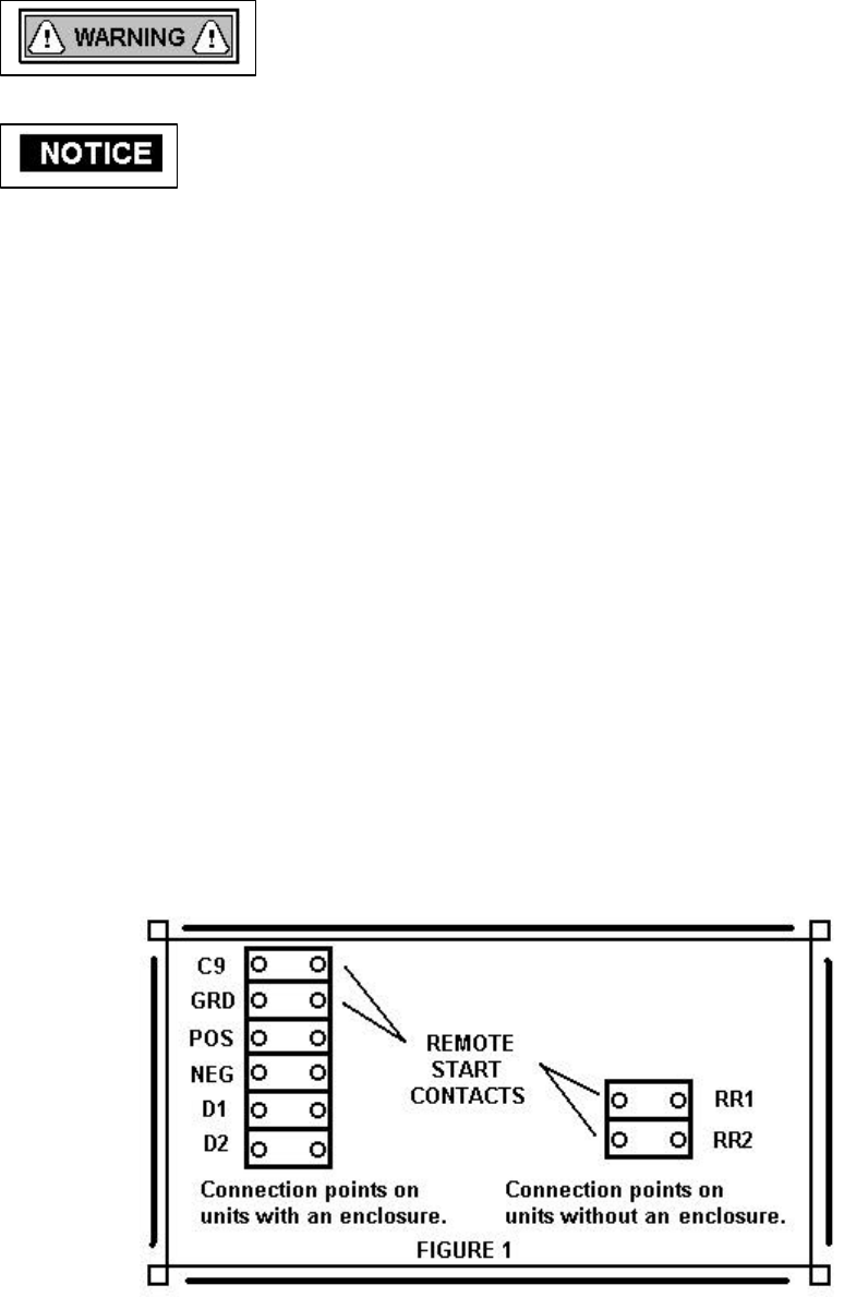
REMOTE START CONNECTIONS
These terminal block- connecting points (See figure 1) are where you connect the two wires
from the remote start contacts of the transfer switch. Once a connection is made across these
connecting points (via the transfer switch or some other switch device), a circuit is completed to
the control logic of the generator set causing the unit to start. The unit will remain running until
this connection is opened. Once the remote start connection is opened, the logic circuitry
allows the engine to run for approximately 60-90 seconds before it shuts off. This time delay is
to allow the engine to run unloaded for a period of time to cool down.