


4
Getting started
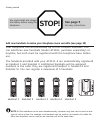
MANUFACTURED IN CHINA
COMPLIES WITH 47 CFR PART 68
REGISTRATION NO.: US:EW7W401B80-565600
RINGER EQUIVALENCE: 0.1B
USOC JACK: RJ11C/RJ11W
HAC FCC ID: EW780-5656-00
THIS DEVICE COMPLIES WITH PART 15 OF THE FCC RULES. OPERATION IS SUBJECT TO
THE FOLLOWING TWO CONDITIONS: 1) THIS DEVICE MAY NOT CAUSE HARMFUL INTER-
FERENCE; AND 2) THIS DEVICE MUST ACCEPT ANY INTERFERENCE RECEIVED, INCLUD-
ING INTERFERENCE THAT MAY CAUSE UNDESIRED OPERATION. PRIVACY OF COMMUNI-
CATIONS MAY NOT BE ENSURED WHEN USING THIS PHONE.
DC 6V 300mA
CLASS 2 POWER SOURCE ONLY
TELEPHONE
EQUIPMENT
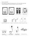
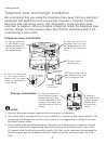
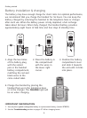
Telephone base and charger installation
We recommend that you install the telephone base away from any electronic
equipment and appliances such as personal computers, computer routers,
television sets, microwave ovens, and refrigerators. Avoid excessive heat,
cold, dust or moisture. When a location is selected, install the telephone base
and the charger as shown below. Make sure that the electrical outlet is not
controlled by a wall switch.
NOTES:
1. Use only the power adapter supplied with this product or equivalent.
2. This power unit is intended to be correctly oriented in a vertical or floor mount position. The
prongs are not designed to hold the plug in place if it is plugged into a ceiling or an under-
the-table/cabinet outlet.
3. If you receive high speed internet service through your telephone line (commonly referred
to as DSL), and you are experiencing interference during conversations and/or your caller
ID features aren’t functioning properly, install a DSL filter to the telephone line between the
telephone base and the telephone wall jack. Contact your DSL service provider for a DSL
filter.
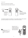
1. Plug the small end
of the smaller power
adapter into the jack
on the underside of the
charger, then route the
cord through the slot as
shown.
2. Plug the
large end of the
smaller power
adapter into
an electrical
outlet.
Charger installation
Telephone base installation
4. Plug the other end of
the telephone line cord
into a telephone jack.
1. Plug the small end
of the larger power
adapter into the power
jack at the bottom of
the telephone base.
3. Route cords
through slots.
5. Plug the large end
of the larger power
adapter into an power
outlet not controlled by
a wall switch.
Power
adapter
2. Plug one end of the
telephone line cord into
the telephone jack at the
bottom of the telephone
base.
DSL filter
(not included)
Telephone
line cord