


2
Operation
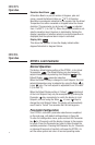
Athena Series OTC25 Digital
Temperature Controller
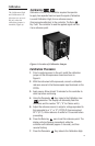
Just a few easy steps are required before your OTC25
can be placed into service. After completing the mounting
and wiring procedures as previously instructed, set each
controller parameter using the simple front-panel keys
as instructed.
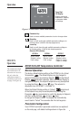
Power On
When power is first applied to the OTC25, all segments
of the LED display, as well as the discrete indicators, will be
momentarily illuminated while the instrument goes through a
series of diagnostic checks to verify proper operation of the unit.
A software version will then be displayed, e.g., . The last
two digits of this code indicate the software revision supplied
with your controller. Please provide this revision number when
contacting us regarding your unit. This display is followed by a
mnemonic code representing the OTC25 model type.
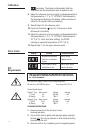
Wiring
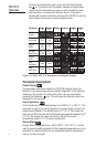
IMPORTANT: All electrical wiring connections should be made
only by trained personnel using Class 1 wiring, and in strict
accordance with the National Electrical Code and local regula-
tions. Both of the incoming power lines should be fused with
2AG, 0.5 A maximum rated fuses.
The OTC25 controller has built-in circuitry to reduce the effects
of electrical noise (RFI) from various sources;
however, power and signal wires should always be kept
separate. We recommend separating wires into one bundle for
power (from line power and output) and one bundle for signal
(from thermocouple).
The OTC25 power supply accepts 100 through 250 Vac and 120
through 250 Vdc line power without any switch settings or
polarity considerations.
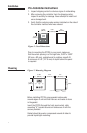
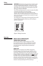
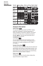
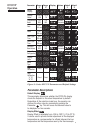
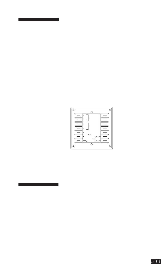
Figure 3. Wiring Connections
OUTPUT #2
OUTPUT #1
COM.
N.O.
N.O.
L1
L2
COM.
T/C
(-)
(+)